
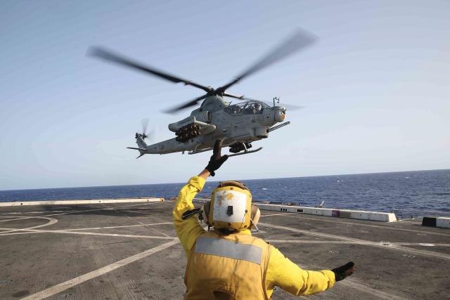
When Navy and Marine Corps aviators operate rotary-wing aircraft on Navy ships, it demands precision and coordination to ensure the safety of both personnel and equipment. The complexities and dangers increase when helicopters return from a sortie carrying ordnance. The U.S. Navy made significant adjustments to shipboard aviation operations following the major fire on the USS Forrestal (CV-59) in 1967 when the negligent discharge of a Zuni rocket resulted in a chain reaction of explosions and a massive conflagration. With ordnance on board, rotary-wing aircraft now fly what is known as an alpha approach, keeping the nose of the aircraft pointed away from the ship during the entire approach and then landing with the nose canted outboard and away from the ship, other aircraft, and equipment.1,2
If done properly, the alpha approach will result in any accidental discharge of ordnance during approach and landing hitting the ocean instead of the ship. Unfortunately, there are no specific markings on the flight deck that precisely guide pilots during these critical operations, heightening the potential for other mishaps. The Navy should add flight-deck markings on the amphibious transport dock (LPD) class ships that specifically guide pilots when conducting flight operations with ordnance to reduce the risk of landing offset from the ship’s base recovery course.
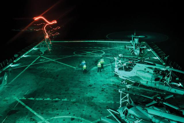
The flight deck is one of the most dangerous places to work, and those who work on it qualify for hazard incentive pay. In 1995, a comprehensive review of flight-deck mishaps between 1977 and 1991 found that 918 personnel were injured and 48 killed.3 The Naval Safety Center at the time (now the Naval Safety Command) published an entire issue of Approach magazine dedicated to flight deck awareness in 2008—a testament to the danger. Approach editor Dan Steber writes, “Each flight deck task has the potential to end in a mishap.”4 On the LPD-class ships, there are typically seven or eight H-1 Huey or Cobra aircraft on board. New flight deck markings would aim to prevent two helicopters’ rotor blades from striking each other, which would likely result in both aircraft being unable to fly for the rest of their deployment or permanently. Furthermore, with up to five other aircraft and more than 20 personnel on the flight deck during flight operations, there is extreme risk of flying debris impacting other helicopters or sailors and Marines. Mishaps injure sailors and Marines, break equipment, and reduce mission readiness.
Normal Operations
When landing on the ship under normal circumstances without ordnance, pilots have dedicated lines to guide them precisely where to land.5 These lines ensure the aircraft do not land too close to the edge of the flight deck, the aircraft next to, ahead of, or behind them. With just 71 feet 4 inches between landing spots, the lines are essential to maintain safe clearance from other helicopters.6 AH-1Z and UH-1Y helicopters have a 48-foot rotor diameter, which leaves just 23 feet 4 inches between two helicopters’ main rotor blade tips when they land on the LPD’s adjacent expanded spots.7,8 For perspective, under normal circumstances ashore, United Facilities Criteria: Airfield and Heliport Planning and Design stipulates the distance between parking spots should be 82 feet.9 Despite the additional challenges of a pitching and rolling deck and wake turbulence coming off the ship’s superstructure, Navy and Marine Corps rotary-wing pilots must accept more risk with 10-plus feet fewer between aircraft at sea.
Alpha Approach Angles
When pilots land on an alpha approach, however, there are no specific flight-deck markings to guide them. They must approximate the angle at which to land the helicopter in relation to the ship to ensure forward-firing ordnance will point offboard. The athwartship line—the line perpendicular to the keel of the ship that H-1 pilots aim to land their skid tows on—is not an effective reference point in the alpha approach because the helicopter is not landing in the direction of the keel. When landing offset, the fore/aft centerline of the ship no longer runs lengthwise through the longitudinal axis of the helicopter, thus no longer providing the pilot a dedicated reference to point the nose. Without any dedicated reference points for landings with ordnance, a pilot must use the currently available landing reference lines and approximate where to position the helicopter safely. Approximating the landing point leads to a less precise landing and more error—at a time when precision is needed to ensure safe clearance between helicopters. Despite these challenges, dedicated references are not present, which ultimately increases the risk to mission, equipment, and personnel.
Coming into the ship on an alpha approach, a pilot must adjust his or her approach to ensure the nose remains canted away from the ship’s superstructure and other aircraft or equipment on the flight deck.10 When the helicopter lands at an angle, the clearance is reduced in one of two ways: either the main rotor mast and tail rotor move toward the center of the ship, or the helicopter’s outside landing gear or skid tube moves closer to the edge of the ship, depending on whether the pilot rotates about the nose of the aircraft or the main rotor mast. (See figure 1.)
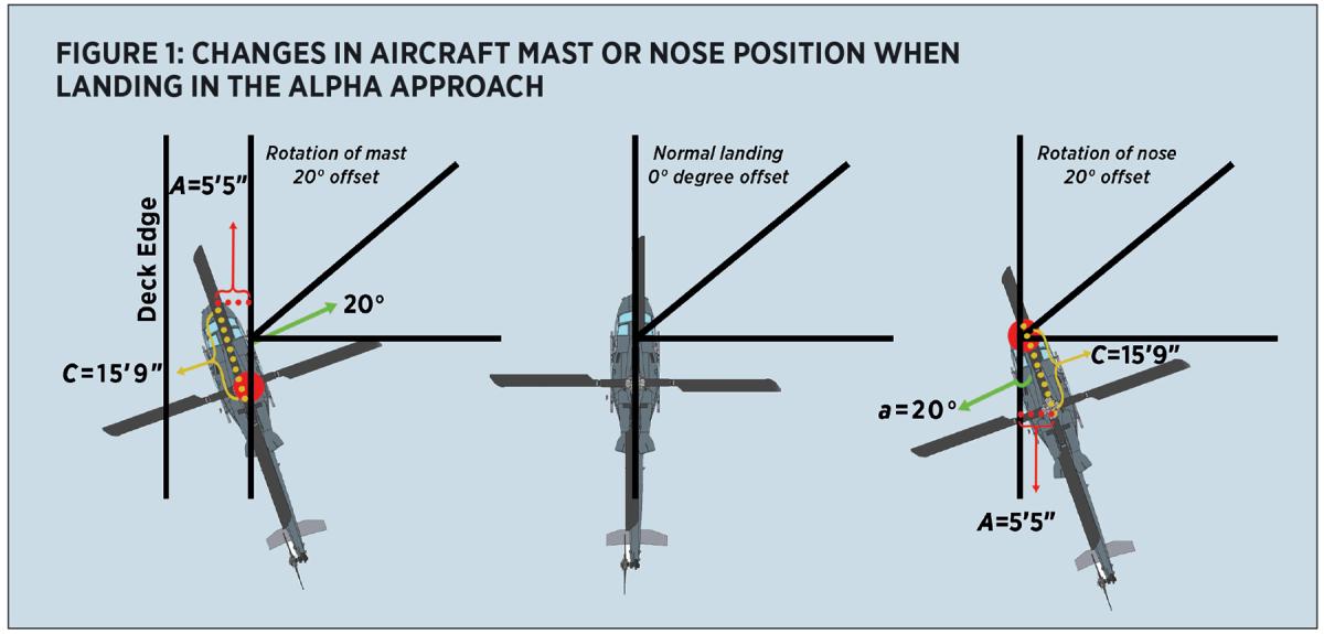
If the pilot rotates about the nose of an H-1 aircraft, then the main rotor mast, located 15’ 9” behind the nose, will move horizontally along the lateral axis of the ship toward an adjacent aircraft.11 Applying the Pythagorean Theorem and the Law of Sines, side A can be calculated using the formula, A=C ×sin (α), where A is the distance the main rotor mast moves toward the center of the ship, C is the distance from the nose to the mast (15’ 9”), and α is the angle of the aircraft offset (20°). In this case, side A is equal to 5’ 5”. If the main rotor mast moves 5’ 5” inches toward the center on the ship, then the main rotor blade tip moves the same distance. If two aircraft adjacent to each other both offset by 20 degrees for ordnance operations, the clearance between the two aircraft is reduced by 10’ 10”, from 23’ 4” to 12’ 6”.
On the other hand, if the pilot chooses to rotate about the mast to prevent the main rotor from closing toward the adjacent aircraft, then the aircraft’s nose and landing gear move closer to the deck edge. The formula remains the same but now A is the distance the nose moves toward the deck edge. With only 10’ 4” inches between the skid tube and the deck edge, a 20-degree angle would leave just 4’ 11”.
While these margins are small, the danger is multiplied as there are no markings specific to guiding the pilot where to land with ordnance to prevent reducing the clearance further. For all other aircraft that conduct shipboard landings, there are markings that guide the pilot to line up longitudinally and laterally.12 For CH-53s and MV-22s, there are wheel boxes—painted rectangles—that specify where each wheel should be placed. For H-1s making normal landings, the pilot has two specific lines that guide where to land left, right, forward, and aft. No such markings exist for H-1s landing offset on the expanded spots. Instead, pilots must approximate the angle that keeps forward-firing ordnance from pointing at the ship and then land with reduced clearances and often with reduced cockpit visibility.
Furthermore, the calculations above fail to account for two elements, the first being pilot error. Despite a rigorous training syllabus, small errors will occur during the most difficult landing conditions. Pilots are often battling pitching and rolling flight decks and air wake turbulence from the ship’s superstructure. In addition, the Navy’s SH-60 airframe has a larger main-rotor diameter, which shrinks the clearance calculated above even more. Without specific lines to show pilots where to land, there is greater potential for errors, near misses, and mishaps.
New Deck Markings
The Navy and Marine Corps should invest in new flight deck markings that give the same reference points that helicopter pilots have during normal landings. The new markings should provide an offset heading from the ship’s keel to line up the aircraft and prevent the tail from being dangerously close to an adjacent aircraft. In addition, there should be marks where the skid tows or turrets should be in this offset position just as there are marks for where CH-53s or MV-22s place their wheels.
New flight deck markings would require funding to upgrade the flight decks on the Navy’s 11 LPDs. The two main costs would be: research required to ensure the markings achieve the intended results; and dedicated inport maintenance to paint the lines accurately. However, the proposed deck markings are additions and would not require any lines to be removed. The investment would reduce the risk of mishaps, potentially saving lives and tens of millions of dollars (in the event of just one mishap).
Added flight deck markings could, however, clutter the flight deck and make it more confusing for pilots during all types of landings. With many lines on the deck, it is possible that additional lines would make it more difficult for pilots to acquire the intended lineup while on approach to the ship. This could be mitigated if the new markings were segmented white stripes, which could be identified easily by pilots as the helicopter crosses the deck edge and stabilizes over the spot.
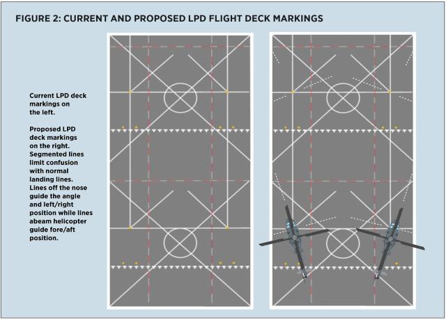
The proposed marking system (figure 2) would give pilots the safe reference points they are accustomed to during a normal landing. Off the nose, a line would guide the pilot to the correct angled position and help center the pilot laterally. To the left and right, a line would guide them from landing too far fore or aft in relation to the desired landing point. The combination would ensure repeatable, precise, and accurate landings during alpha approaches.
1. Naval Air Systems Command, NAVAIR 00-80T-122: Aircraft Operating Procedures for Air-Capable Ships NATOPS Manual, (NAS North Island, California: NAVAIR, 2021).
2. Naval Air Systems Command, NAVAIR 00-80T-126: Aircraft Operating Procedures for LPD/ESB Ships Preliminary NATOPS Manual, (NAS North Island, California: NAVAIR, 2021).
3. Scott. A. Shappell, “Naval Flight Deck Injuries: A Review of Naval Safety Center Data, 1977–91,” Aviation, Space, and Environmental Medicine 66, no. 6 (June 1995).
4. Dan Steber, ed., “The Workplace,” Flight Deck Awareness, 5th edition, 2008.
5. Naval Air Systems Command, Aircraft Operating Procedures for Air-Capable Ships NATOPS Manual.
6. Alvin Corbett and Kiera Wells, Naval Air Warfare Center Aircraft Division, Shipboard Aviation Facilities Resume, (Lakehurst, New Jersey: NAWCAD, 2020).
7. Naval Air Systems Command, NAVAIR 01-110HCG-1: NATOPS Flight Manual Navy Model UH-1Y Helicopter, (Patuxent River, Maryland: NAVAIR, 2020).
8. Naval Air Systems Command, NAVAIR 01-H1AAD-1: NATOPS Flight Manual Navy Model AH-1Z Helicopter, (Patuxent River, Maryland: NAVAIR, 2020).
9. Department of Defense, Unified Facilities Criteria: Airfield and Heliport Planning and Design (Washington, D.C., Department of Defense), 2020.
10. J. M. Caiella, “Dissecting a Carrier Disaster,” Naval History, August 2022.
11. Naval Air Systems Command, NATOPS Flight Manual Navy Model UH-1Y Helicopter.
12. Naval Air Systems Command, Aircraft Operating Procedures for Air-Capable Ships NATOPS Manual.


