In the late 19th century, naval artillery was improving by leaps and bounds, and rifled breech-loading guns were being adopted as the naval weapon of choice. These guns fired forged steel projectiles that could, in theory, hit a target at nearly 10,000 yards, many times the range possible with the old smoothbore muzzle-loading cannon that had been the staple of naval warfare for centuries. While these ranges were possible under controlled conditions on the proving ground, obtaining such a hit at sea against a moving target was a significant challenge.
Naval writers at the time noted the importance of hitting the enemy first to disable his ships at the earliest opportunity. Firing should therefore commence as soon as hits were possible. This meant opening fire at long range, which at the time was considered 2,000 yards and beyond. While the guns had the potential to hit well beyond this range, it was difficult to estimate an accurate range at long distances, an activity known as “rangefinding.”
Artillerists had for many years used a variety of techniques to estimate the distance from their guns to the target, mostly relying on a “trained” eye. After setting the initial gun elevation based on an educated guess, they would make adjustments after observing the fall of shot. Gunnery officers eventually realized that an observer could measure distance with a degree of accuracy using a method known as stadiametric rangefinding. This involved solving for the distance along the side of a right triangle, with the observer at the apex. Using the height of an object—such as a ship’s mast—as the base, and measuring the vertical angle between the waterline and the top of the mast.
The main drawback to this method was that one had to know what the height of the object was to solve for the distance. Gunnery observers stationed in the upper works of a ship could measure the angular height of an object with a sextant, consult standard references on foreign ships to determine the mast height, and then use tables to convert the measurements into distance using trigonometry. This method was time-consuming and, under combat conditions, prone to error; a clever opponent could also change his mast height to render such estimates inaccurate.
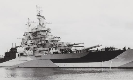
In the late 1880s, U.S. Navy Lieutenant Bradley A. Fiske, an inventive genius, began to look at the problem with an eye toward increasing rangefinding speed and accuracy, which led him to develop two new devices. In 1890, he invented what he called the stadimeter, essentially a sextant laid on its side, that enabled the observer quickly to make a measured estimation of range. Handheld and light, it was easy to use, but its accuracy depended on knowing the base height of the target. With its limited magnification, it was useful only for relatively short ranges. Even so, Fiske used this device to estimate ranges during the May 1898 Battle of Manila Bay, and versions were later incorporated into submarine periscopes. During World War I, Allied ships adopted dazzle paint schemes and modified masts and funnels in an attempt to confuse the rangefinding efforts of U-boat commanders.
Fiske’s other rangefinder invention flipped the triangular measurement around: Two observers located at a known distance apart in the upper works of a warship formed the base of a triangle with the target as the apex. Each observer would rotate a telescope on a base plate to observe the target simultaneously. In the base plate were electrical resistors that measured the varied current passing through them, providing angle measurements that allowed the range to be read directly from a calibrated galvanometer. Fiske patented the device and set up a company to sell it to the U.S. Navy and any foreign government that might be interested. His rangefinder was installed on a number of U.S. and French warships as a trial, but it was never officially adopted by either navy because the device suffered from electrical problems at sea, and locating it in a ship’s military masts made it vulnerable to enemy shellfire.
The Royal Navy also tried Fiske’s electrical rangefinder and found that it did not meet their requirements, but they were sufficiently impressed (or alarmed) by its possibilities that, in 1892, the service requested Barr and Stroud Limited of Glasgow, Scotland, to further develop a rangefinding device the company had designed for use for the British Army.
Barr and Stroud’s new rangefinder combined the portability and ease of use of the sextant with the greater accuracy of the dual telescopes of the Fiske device. It was cheaper to build, required only one operator, and was not subject to the vagaries of electrical measurement, a technology still in its infancy. The original versions of Barr and Stroud rangefinders were small and light enough to be held by the operator or mounted on a simple wooden tripod, allowing one to be used anywhere on the ship. Unlike later models, it did not require the operator to have excellent stereoscopic vision. The device was found to be so successful that the Royal Navy immediately ordered six for further evaluation, eventually placing orders for enough to equip every major ship in the fleet.
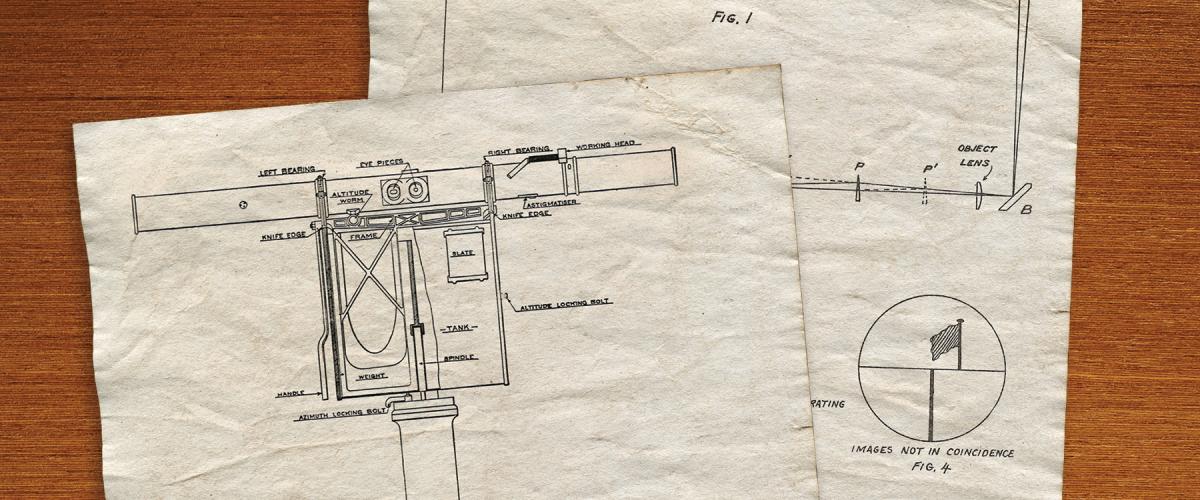
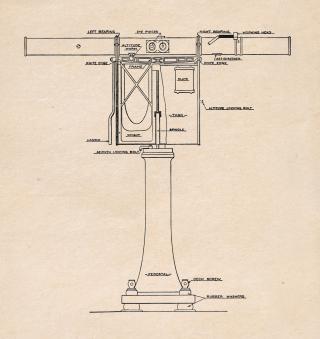
The earliest Barr and Stroud rangefinder consisted of a sealed tube 3½ inches in diameter, with two round glass windows located on the front of the tube at either end, with a base length of 4½ feet. At the center of the back side of the tube were two eyepieces the operator looked through as if looking through a set of binoculars. The windows at each end admitted light to mirrors set at 45 degrees that reflected it through a telescopic objective lens inside the tube to a central prism that bent the light into the right eyepiece, in effect putting two telescopes together, located end to end. The left side eyepiece looked through a low-magnification lens mounted on the front of the tube, offset from the center, which allowed the operator to find the target.
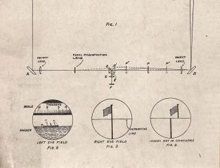
Although the eyepieces resembled binoculars, the operator was seeing two different images, each split horizontally as in a sextant. In the left eyepiece, the operator saw a range scale over an image of the target; in the right one, he saw a high-power magnification of the target split horizontally. The lower image was reflected from the left, entering at a right angle to the base line. The upper image coming from the right was along the hypotenuse of the right triangle. As with a sextant, the operator turned a knob until the upper image coincided precisely with the lower image and then read the range from the scale in the left eyepiece. Turning the knob moved a deflecting prism located in the light path in the right side of the tube, which, in effect, made a minute angular measurement when the images were made to coincide. The deflecting prism was connected to the range scale, and the device was calibrated to do the math for the operator.
In 1906, an improved, nine-foot version was specified for HMS Dreadnought, mounted on a swiveling base. The range error for the shorter original version was given as 1 percent at 3,000 yards; doubling the base length to nine feet gave the same margin of error but out to 7,000 yards. As the need for greater gunnery ranges increased, so did the base length of the rangefinders, and very large rangefinders eventually found their way into gun turrets and fire-control directors.
The U.S. Navy adopted the Barr and Stroud rangefinder in 1903, as did the navies of Japan and Austria. However, preferring a domestic supplier for such an important instrument, the U.S. Navy was soon procuring rangefinders from Bausch and Lomb. These operated on the same basic principles as the Barr and Strouds but incorporated improvements that made them less susceptible to shock and easier to adjust.
At the Battle of Tsushima, fought on 27–28 May 1905, the Japanese put their Barr and Stroud rangefinders to good effect pummeling the Russian Second Pacific Squadron in a historic defeat, demonstrating the value of rangefinding to success in battle.
Sources:
Officers of the United States Navy, Textbook of Ordnance and Gunnery 2nd ed. (Annapolis, MD: United States Naval Institute, 1905), 463–68. Ordnance Pamphlet no. 357: Rangefinders, U.S. Navy, (Washington, DC: Navy Department, February 1913), 33–35, Plate 1.
David K. Brown, Warrior to Dreadnought: Warship Design and Development 1860 to 1905 (Barnsley, UK: Seaforth Publishing, 1997), 181.
Bradley A. Fiske, From Midshipman to Rear Admiral (New York: The Century Co., 1919), 121–24, 208–9.


