
In June, 1917, two months after the entry of the United States into the World War, no definite air policy or program had been adopted by this country. This condition was due to the lack of any conclusive information regarding the work of the Allied Governments along these lines, and to varied and contradictory recommendations which had been received from the War Departments and the Admiralties of Great Britain and France as to the types of planes which should be adopted by this country. To remedy this condition an informal joint Army and Navy Board was appointed to proceed to Europe and to make a study of air matters among the principal governments engaged in the war against Germany, and to recommend the steps to be taken by our government in building up its own air services and in carrying out a definite air policy.
The personnel of this committee was Major R. C. Bolling, Captain V. C. Clark, Captain E. S. Gorrell, Captain Howard Marmon and Captain Hughes representing the army, and Lieutenant W. G. Child and the writer representing the navy. In accordance with instructions to the committee, they proceeded to Europe, arriving in London the latter part of June. At this time, the naval activities of the U. S. Government were directed mainly against the submarines. The center of naval activities was the American Embassy in London, and by this time the naval officers had become keenly aware of the grave menace of the German submarines. At the embassy all discussions centered around this subject, and it was evident that fuller methods of combating the submarine must be provided and provided very quickly. Accordingly, we began a particular and detailed study of the types of aircraft for use against the submarine menace. This study was carried on in England, in France, and in Italy, and, as a result of this study, it was concluded that the quickest way for the navy to obtain results in the air would be with kite balloons, for observation purposes, anchored to a destroyer or some other type of patrol vessel, and with seaplanes of the flying boat type, as differentiated from the hydroaeroplane, for patrol purposes and for the bombing of submarines.
At this time, the largest flying boat in use for patrol work was the H-12, a craft equipped with two Rolls-Royce motors, with a lifting capacity of approximately 9000 lbs., and a cruising radius of slightly over 500 miles. This type of boat had proved successful in patrol work, except for its limited cruising radius. Because of the fact that the regions in which submarines were active were often a considerable distance from the naval air bases, the entire time available for patrol was often used in flying to and from a base. It was very desirable that larger craft should be provided, craft which could not only carry a heavy load of bombs, but which also had sufficient radius of flight for the trip from the naval bases to the patrol regions and return.
The writer returned to this country on September 1, 1917, and on September 2 reported the results of the investigations to Rear Admiral D. W. Taylor, the Chief of the Bureau of Construction and Repair. Admiral Taylor had been much interested in the work of the larger flying boats, and his parting injunction to the writer before his departure for Europe was to examine carefully the work being done along the line of flying craft much larger even than any then in use. When the report with its recommendations had been presented to Admiral Taylor, he immediately went far beyond any recommendations which had been made, and ordered the design of a flying boat able to fly itself, if possible, across the ocean. This would mean the capacity to proceed before daylight from a seaplane base to the patrol area, to spend the day in patrol work or in convoy, and to return to its base after dark. In addition to this, it must be able to carry several bombs of a size sufficient to increase very materially over the possibilities of that day the danger zone in the bombing of submarines.
All the information made available regarding the design and construction of flying boats of great size indicated the enormous difficulty of such a project. The trend of opinion of the European air ministries was against such large sizes, and, as far as the methods of construction and the motor powers available at that time were concerned, the limit of size had been practically reached. On the presentation of these facts to Admiral Taylor, and the pointing out to him of the possibility of failure of such a project, he declined absolutely to be interested in this phase of the problem, and in his characteristic manner closed the discussion he was having with Naval Constructor Hunsaker, head of the Construction and Repair Aeronautical Section, and the writer, with instructions to “get busy and produce results.”
This was the inception of the design of the NC type of flying boats. After a conference between Naval Constructor Hunsaker and the writer, it was decided to call upon Mr. Glenn Curtiss, at that time the American most experienced in the design and construction of seaplanes, for his suggestions as to the type of seaplane which might best fulfil the requirements. In obedience to a request from Admiral Taylor, Mr. Curtiss came to Washington, and, in a conference between the naval officers above referred to and himself, it was decided to give consideration to the possibilities of a seaplane capable of sustained flight from Newfoundland to Ireland, if possible, or at least capable of flight from Newfoundland to the Azores. Certain definite conclusions reached by the bureau regarding the probable type of such a seaplane were given Mr. Curtiss for his examination.
Within a few days after this conference, Mr. Curtiss returned to Washington with preliminary plans for two types of flying boats, embodying in their general characteristics the conclusions of the bureau—one a five motor 1700 horsepower machine, and the other a three motor 1000 horsepower machine. Both were biplanes, similar in design, and differing only in size, the size being dependent upon the available horsepower. The hulls of these machines differed greatly from the conventional design. They were much shorter than the conventional boat hull, were shaped more like the pontoon of a seaplane, and with the intention that the tail surfaces instead of being supported by the hull would be carried by a system of outriggers in part from the upper wing beams, and in part from the stern of the hull. These suggestions covered rough sketches only of the proposed machines, together with certain estimates based on extensive experience as to weights and sizes. Admiral Taylor was in favor of the larger boat. The writer, however, due to his experience in airplane construction, his familiarity with the limitations in manufacturing facilities, and because of the small experience of our designers, and of uncertainties regarding the availability of suitable engines, argued in favor of the smaller craft. The final decision was to not attempt the construction of the larger size of 1700 horsepower but to stick to a smaller one of approximately 1000 horsepower.
In taking up the design of such a seaplane, it was very evident that radical changes in the method of design must be followed. With the methods of design at the time almost generally employed, the limits of size had been practically reached. The largest machine at that time in use was the Handley-Page night bomber. In the design of this airplane new and advanced methods had been employed, and to its study much consideration was given. This machine had a total lifting capacity of 11,000 lbs. and was equipped with two 275-horsepower Rolls-Royce motors. The dead weight was approximately 6600 lbs., and the allowable weight for oil, gasoline, cooling water, crew and miscellaneous supplies, which grouped together are called by the name of “useful load,” was 4400 lbs. This made the value of the useful load 40 per cent of the gross load, which was the maximum percentage which had been obtained in any large machine. Naval Constructor Hunsaker in estimates which had been made of various planes of an average lifting capacity of 2500 lbs. had found that the percentage useful load was from 30 to 32 per cent. The proposed design for the 1000-horsepower flying boat called for a total load of approximately 25,000 lbs. In comparing this machine with the Handley-Page night bomber, it was apparent that the design of the Handley-Page would have to be improved upon and the percentage of the useful load made at least as high if this design was to be considered successful. One possibility of improvement of the design was in the use of the Liberty motor which was at that time undergoing its first tests, and which gave promise of being lighter for its power that any other motor then in use.
It has been found in the design and construction of large airplanes and seaplanes that the unescapable dead weights, such as engines, propellers, radiators, gasoline and oil tanks, crew, etc. which must be allowed for, require, in a completed plane which will carry them successfully, a total weight of, roughly, from three to four times the sum of these dead weights. If in any manner, such, for example, as by a reduction of the weight per horsepower of the motor, 100 lbs. can be saved in the weight of any of these parts, there can be a reduction in the total flying weight of the machine of from 300 to 400 lbs. or else a considerable increase in the weight of gasoline which can be carried. There were also possibilities of reduction in weight of structural elements, such as wing beams, ribs, wing struts, compression struts, fittings, etc. If by any method of design it were possible to reduce the weights of these parts without reducing their strength, there would again be a gain in the fuel carrying capacity of the machine over that possible with methods of construction at that time in use.
The points outlined above give some idea of the problem of design which it would have been necessary for the Bureau of Construction and Repair to handle in the preparation of plans for this boat. Because of the insufficient technical force at the bureau, and the difficulty in increasing this force, it was decided that the best method of procedure would be to transfer the physical work of the design of this machine to the Curtiss Aeroplane and Motor Corporation at Buffalo. The Curtiss Aeroplane and Motor Corporation was the only aeronautical manufacturing company which had a well organized design force in any way capable of handling this problem. On the transfer of this design to the Curtiss organization, it was intended that the navy would exercise close control over the design, and that the Curtiss organization should work out all details under navy supervision.
When plans for the design had been carried this far, it became necessary for Admiral Taylor to obtain the cooperation of the other bureaus which would be concerned in the construction of such a craft, and to obtain the approval of the Secretary of the Navy. The Division of Operations and the Bureau of Steam Engineering agreed to the carrying out of these plans, and the entire proposition was then submitted to the Secretary of the Navy. The secretary approved the proposal which had been made, and it was then possible to proceed upon the definite work of design. Accordingly, a contract was made with the Curtiss Aeroplane and Motor Corporation on the basis of cost plus a fixed profit on the determined cost. Such a contract was necessary because no design similar in nature to this had even been attempted, and there were no figures available which could give even an approximate estimate of the cost of such a design. The contract as arranged provided that all labor and material should be charged directly to the contract. To this charge 100 per cent would be added to cover intangible and indirect expenses which could not be definitely estimated; and, to the sum of these two amounts, 10 per cent was to be added for profit. This proposed contract was satisfactory to both the navy and the Curtiss Aeroplane and Motor Corporation, and work was started upon the design early in October, 1917. The design work was later transferred to the Curtiss Engineering Corporation at Garden City, Long Island, where it was completed in January, 1918.
At this time it became necessary to choose a name for this type of flying boat. Inasmuch as the design work was under the supervision of the navy but was being carried out by the Curtiss organization, it was decided that the name of the type would be the NC-1, N standing for navy and C for Curtiss, and the 1 representing the first boat designed under this arrangement between the navy and the Curtiss Company. It was intended calling specific boats of this type NC-1, No. 1, NC-1, No. 2, etc., but as this has proven awkward in use the type is now known as the NC type, and the specific boats as the NC-1, NC-2, etc.
The method usually followed until a year or two ago in the production of new types of flying boats, and for new types of airplanes in general, had been to make sketches of the proposed type of plane and of some of the more important elements and details, estimate the probable weight, and then to proceed immediately upon the construction of parts. If the completed machine did not give satisfactory operating characteristics, certain parts would be changed and it would be tried again. This method would be continued until the design proved to be entirely unsuited for practical use or some satisfactory compromise was reached. With such an unscientific method of design it is exceedingly difficult to determine why a plane fails to come up to the estimated performance. If the weights are excessive, it is difficult, or even impossible, to determine wherein the excess lies, or how to change the construction to make a reduction. If the speed of the machine fails to come up to expectations, it is practically impossible to determine what changes can be made.
In the design discussed, due to the great increase in size over any successful boat previously constructed, and to the necessity of increasing the percentage of useful load above any which had been reached in flying boats, the adoption of the method of procedure as outlined above would have made failure certain. It was determined to have every detail designed carefully, according to the best engineering practice, and to have the design practically completed before any construction work was commenced. It was only in this way that it would be possible to arrive at a design which would give a practical certainty of a flying boat coming up to the requirements laid down by Admiral Taylor, or which failing in this would show definitely and exactly to what failure was due.
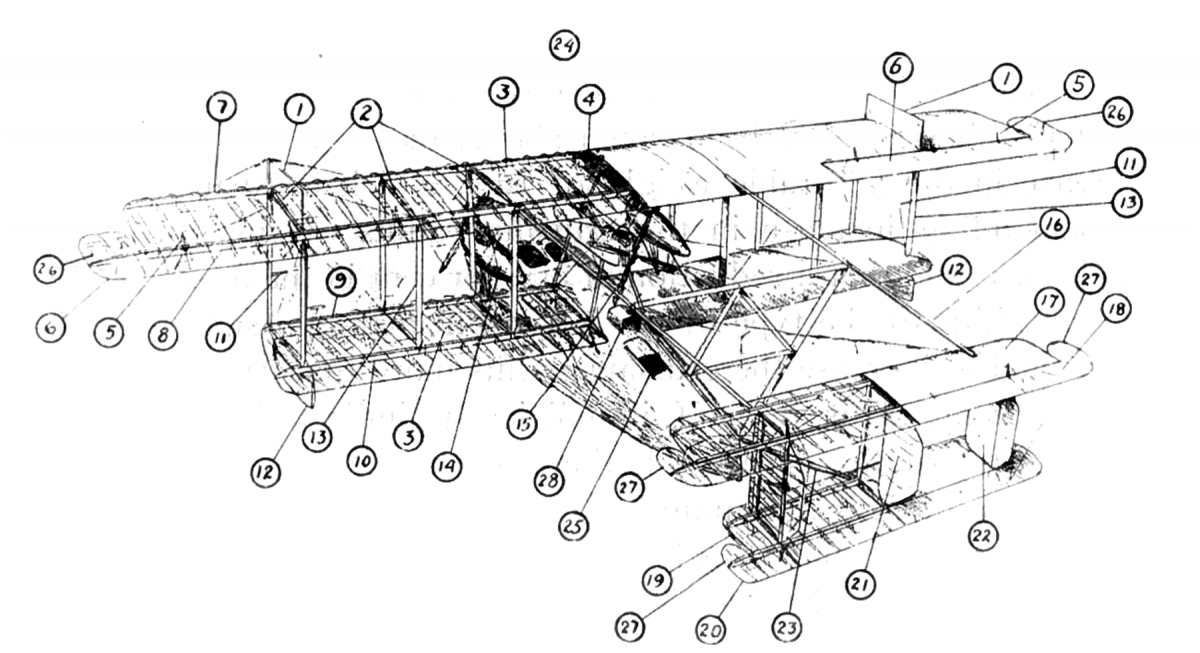
- Non-skid Fin.
- Compression Struts.
- Wing Ribs.
- Gravity Tank.
- Aileron Horn.
- Aileron.
- Forward Beam—Upper Panel.
- Rear Beam—Upper Panel.
- Forward Beam—Lower Panel.
- Rear Beam—Lower Panel.
- King Post Brace—Outer Struts.
- Wing Tip Pontoon.
- Wing Struts.
- Outer Nacelle.
- Pusher Propeller.
- Outrigger.
- Upper Horizontal Stabilizer.
- Upper Elevator.
- Lower Horizontal Stabilizer.
- Lower Elevator.
- Balanced Rudder.
- Vertical Stabilizer.
- Tail Boom.
- Pilots’ Seats.
- After Hatchway.
- Balancing Section—Ailerons.
- Balancing Section—Elevators.
- Aluminum Shield under Pusher Propeller.
In the design of any type of airplane two factors are of major importance. One of these factors is weight. The relation between weight, effective lifting surface, and the speed of flight, may be expressed by means of an equation, L = Ky AV2, where L represents the total weight in pounds, A is the total effective area of all supporting surfaces expressed in square feet, V is the speed expressed in miles per hour, and Ky is a constant depending for its value upon the construction of the machine. For any total allowable weight of the plane, every reduction in weight of structural members, as has been noted above, means a corresponding increase in the allowable weight of fuel, which in turn means a corresponding increase in the cruising radius of the craft. It has been found that a reduction of one per cent in the dead weight of a machine of the type of the NC-1 will make possible enough more fuel to increase the cruising radius more than two and one-half per cent. This, in itself, is sufficient to indicate how valuable in the work of the designer is the effort to keep the weights of parts down to their minimum.
The other factor of such great importance is the resistance to the passage of the machine through the air. This resistance is made up of two parts, the resistance of the wing panels and control surfaces, and the resistance of other parts, such as wires and cables, wing struts, nacelles, boat hulls, etc. The resistance of a wing panel has a certain very definite value for each type of wing surface, and has been very accurately determined for all the different types of wing sections. The other resistances, which are grouped together under the general term of “parasite “resistance, must be calculated for each separate part, taking into account the size and length of the part, and its position with respect to the direction of motion. From tests which have been made, the values of coefficients for use in calculating these resistances have been very accurately determined, and the total resistance or “drag,” which is the term used to represent the combination of wing panels and parasite resistances, may be calculated. The resistance for any individual part may be expressed by means of an equation similar to the one used above for the total lift or weight. This equation may be written D = Kw AV2, where D represents resistance expressed in pounds, V is the velocity of motion in miles per hour, A represents an effective area of all parts producing the resistance and Kw is the co-efficient referred to above. The total drag
is the summation of these resistances, plus the wing panel resistances. The horsepower required to move the plane through the air at a given speed is then determined from the expression: Horsepower = (Drag × velocity) ÷ (375 × eff) where drag is the total drag in pounds as calculated above, velocity is expressed in miles per hour arid efficiency is the propeller efficiency, which in turn depends upon the velocity and the revolutions per minute of the propeller.
The original plans discussed with the representatives of the Curtiss organization called for the design of a flying boat capable, if possible, of sustained flight from Newfoundland to Ireland. As soon as the design had progressed far enough, accurate calculations of weights and resistances were made. Upon the completion of these calculations, it was found that although the total weight came within the specified limits of 25,000 lbs., the total resistance was so high that, with the horsepower available, the speed would be cut down to such a low value that the estimated cruising radius instead of being the 2000 miles required for going from Newfoundland to Ireland, would be not more than 1300 miles. There seemed to be no possible way by which the amount of this resistance could be reduced and, because of this fact, the design of a flying boat capable of flying from Newfoundland to Ireland had to be abandoned as impracticable, temporarily at least. The design was now taken up on the basis of a total weight of 22,000 lbs. and a cruising radius of 1300 miles.
It would have been possible at this time to take up in detail calculations for a five-motored flying boat, as previously suggested by Mr. Curtiss. .Difficulties which had been met with in the design of the three-motored craft had shown, however, that the original decision regarding size and horsepower had been wisely made and that it was better to continue the work with the three-motored type of craft, even though its cruising radius were limited to 1300 miles.
It was necessary to carry on a considerable number of very complete investigations to determine the sizes and shapes of parts to be used in the construction and the materials of which these parts should be made. These investigations had to do with the choice of wing beams, wing struts, wing ribs, compression struts, metal fittings, outriggers for the tail support, and various other parts to be used in the construction of the hull and tail surfaces.
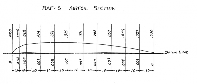
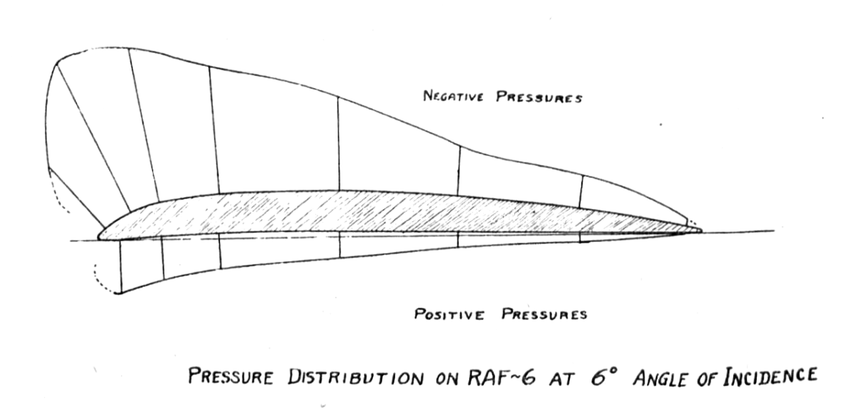
Before a choice of materials to be used in the manufacture of the parts of the wing panels could be made, it was necessary to determine the shape of the wing panel section to be used in the construction. After consideration of various sections, it was decided to make use of the wing section known as the R. A. F. 6, a section designed and used extensively by the Royal Aircraft Factory of Great Britain. This section has a good lift factor, and the lift-drag ratio, which represents the efficiency of the section, is high. Another factor which determined the choice of this section was the depth of the section itself. Due to the large span of the proposed seaplane, the wing beams must, of necessity, be of considerable depth to give the necessary strength, and, inasmuch as the beams are enclosed within the wing structure, it was necessary to have a wing structure which in itself had the requisite depth.
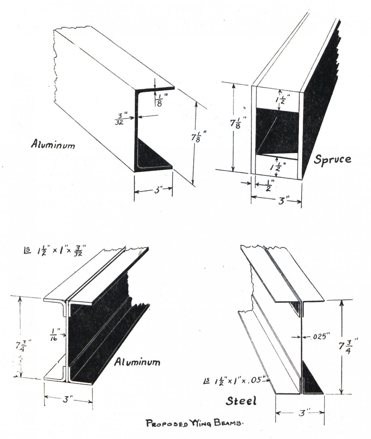
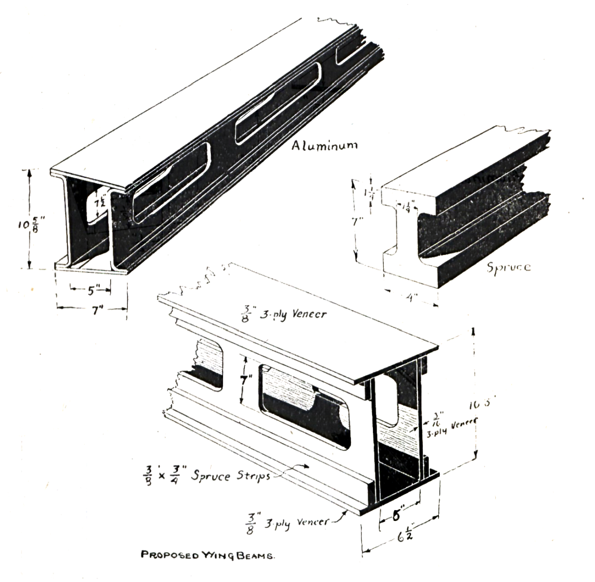
In the choice of the wing beams to be used, beams built of steel, aluminum and spruce, of various cross, sections, were investigated. The more important types of these beams are shown in the accompanying sketches. The total depth of the beam was to be approximately 10 inches; the total length of the beam in the upper outer panels was to be approximately 45 feet; and it was required to carry a load of 190 lbs. per running foot. As the final choice, to meet these requirements, a spruce beam built up in the form of a box was selected as the one which would be most satisfactory in construction and in operation. This choice was based upon weight for a given strength, upon availability and dependability of material to be used in construction, upon ease of construction, and upon the stiffness of the beam for the required depth.
In the choice of wing ribs, ribs built up of aluminum, of steel and of spruce were considered. Based upon weight alone, the choice would lie with the aluminum rib. Weight, however, is not the only factor which must be considered in the choice of the wing rib to be used. With aluminum, there would be danger of deterioration due to the effect of moisture; there would be great difficulty in making satisfactory connection of the several parts of the rib structure; and there would be difficulty in obtaining aluminum which could be depended upon as uniform in structure and in strength. For these reasons, the use of aluminum for construction of wing ribs, as well as for construction of other strength parts of the machine, was decided against.
The second choice on a weight for strength basis of material to be used in the construction of the wing ribs was spruce. Due to the depth of the wing section, and due to the chord of 12 feet, the best construction seemed to be one in which the rib was built up of spruce capstrips, used to form the upper and lower surfaces, joined together by means of small vertical and diagonal spruce members arranged in the form of a truss construction. This construction is very similar to that of the Handley-Page rib, which it had been the writer’s good fortune to be able to examine during the trip to Europe which has been mentioned previously.
In this rib great importance attaches to one of the constructional features. At all joints between the vertical and diagonal truss members and the capstrips, a linen wrapping is used. It is fastened to the spruce members by means of Keystone glue; causes them all to act in unison; and produces a most appreciable increase in strength and in reliability. Actual tests have shown that the use of the linen wrappings practically doubles the strength of the rib.
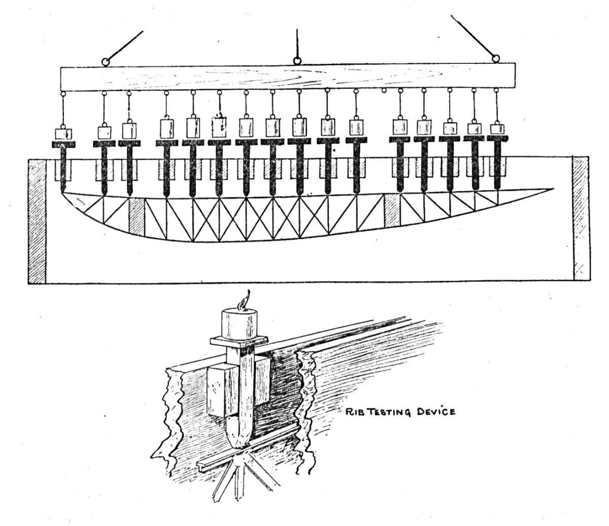
Before the exact type of rib and the sizes of the parts were decided several sample ribs were built up and tested. The method of testing, and the machine used in supporting the rib during the test, are shown in the accompanying sketch. For each wing curve there is a definite distribution of load above and below the wing panel from the leading edge to the trailing edge. By proper distribution of this load along the rib, weights may be determined which will represent the loads acting at the joints of the truss members and these weights may be so calculated as to give these members their normal loading or any desired excess loading. In the tests made, as in the design of all parts of the machine, except wires, it was assumed that a factor of safety of four would be required.
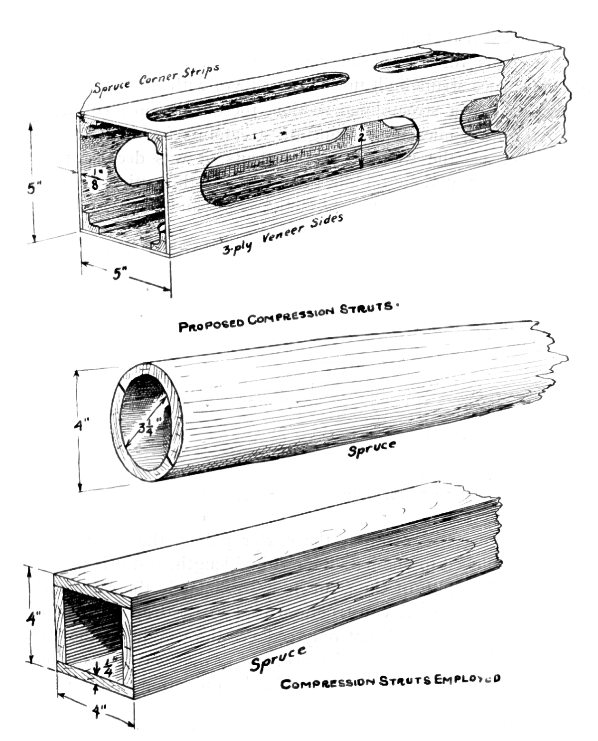
In the design of the compression struts, it was assumed that these struts would have to carry a total flying load equal to approximately one-third of the total weight of the machine, or, in round numbers, 7000 lbs. In the investigations made to determine the most desirable compression strut, it was found that aluminum with a circular section was the lightest for a given strength, but because of the reasons stated above, the aluminum was not chosen. The next most desirable strut was a spruce strut of a circular cross section, tapering in each direction from the center towards the ends. Because, however, of the difficulty of building such struts, it was decided that the one which would be most satisfactory was a spruce strut of a square cross section, built to taper from the center toward each end. Special pin jointed metal fittings were attached to the ends of these struts, and these fittings attached to fittings through the wing beams at the neutral axes.
In the investigation of the shapes and materials to be used in the construction of the wing struts, it was found that steel struts of circular cross section, suitably streamlined, would be very light. The main disadvantage of these struts was in the extreme thinness of the metal to be used in their construction, if the weight for a given strength was to be kept below that of the spruce struts. This also was true of aluminum struts. Because of these facts it was decided that the most satisfactory struts would be routed spruce struts for the engine section panels, and, for the other panels, spruce struts built up in a box form with the sides curved to conform to a streamlined section, these built up struts to be covered with a micarta covering of streamline form.
To decrease the weights of the struts, it was decided to tie them together at their middle points, across the entire length of the wing panels, parallel to both the front and the rear beams.
By so bracing the struts at the center points, the unsupported length is reduced to one-half the original length, and it is possible to reduce the width of the strut in approximately the same ratio. This is similar to the construction used in the Caproni biplane. This reduction in width not only reduces the weight of the strut but also reduces the head resistance, and in that way gives double advantage in the construction and in the operation of the plane. To make possible the bracing of these struts across the entire length of the wing panel, it is necessary to reinforce the outside struts to prevent them from bending. This reinforcing is accomplished by means of a kingpost at the center, guyed by bracing wires running to the upper and lower ends of these struts.
Among the parts of the airplane structure requiring the greatest amount of study are the metal fittings used in fastening the parts and the subjection of these parts to various heat treatments, it was decided that a vanadium alloy steel with an ultimate strength of 150,000 lbs. per square inch would be the most satisfactory for this use. To obtain this strength, it was necessary to subject the parts to a special heat treatment.
This heat treatment must be carried out very carefully, and it has been found during the process of manufacture that a great many parts have been spoiled. As a result of the destruction of so many parts during manufacture, and of the doubts felt by some persons of the absolute reliability of heat treated steels, there has been extended discussion of the advisability of using such steels for these fittings. Inasmuch as a saving of approximately 200 lbs. in weight was secured in this way, this use has been justified. It is certain such use of high tensile steels will continue, as in airplane design the engineer must take advantage of all opportunities afforded by the materials with which he works.
During flight the stresses in the various parts of the wing panel structure are transmitted along the wing panels to the hull by means of the flying wires. During combat it is very possible for one or more of these flying wires to be cut by gun fire. To prevent, as far as practicable, the destruction of the machine due to the cutting of any one of these wires, the design called for these stresses to be carried by three wires in parallel instead of a single one. In later designs, when the need for war purposes had passed, this was changed, and the load was carried by two wires in parallel instead of by three. By this change considerable weight and much resistance were removed. It was planned in the original design to have the landing wires, which carry the stresses due to the weight of the wing panels when the machine is landing or at rest, made up of two wires in parallel, but when the flying wires were reduced to two, the landing wires were reduced to a single wire. These landing and flying wires are made of a non-flexible steel cable varying in size from 3/8 inch to 1/8 inch in diameter. To reduce the resistance of these wires to a minimum, those in the wing truss construction are streamlined. For the double wires a routed spruce streamlining is used, and for the single wires a special one of rubber.
In the design of the hull, certain requirements must be met. These requirements may be briefly discussed as follows: The hull must have sufficient buoyancy to support the weight of the craft when on the water. The usual requirement in hull construction is that there shall be a reserve buoyancy of 500 per cent. The hull must have enough stability to keep the wing panels, propellers, and tail surfaces well clear of the water, and must provide reserve stability for possible operation in strong wind or in a rough sea. As the position of the plane changes, the position of the center of buoyancy must change quickly enough to provide this stability, and to bring the machine back to normal. The hull must be of such a design as to steer readily, especially at moderate speeds, on the water. The bow of the hull must be so built as to prevent nosing under at high speed in rough water or in a bad landing. It should also be so designed as to prevent the throwing of spray during taxiing or planing. This throwing of spray may be prevented to a large extent by the use of thin strips known as spray strips along the sides of the bow.
The shape of the bottom of the hull is of great importance in the operation of the machine. It has been found that a wide bottom planes very quickly. A flat bottom planes quickly, but is unstable, and is likely to cause fore and aft rocking of the machine during planing, which is known as “porpoising.” The V-bottom eases entrance and getaway and prevents porpoising, but is very likely to throw large quantities of spray. A concave V-bottom has the same advantage as the V-bottom but is difficult to handle, especially in making a skidding landing. Considering all points, the V-bottom is the most satisfactory in its actual use.
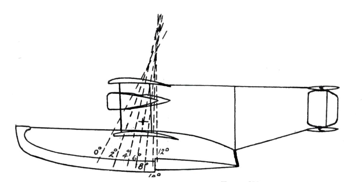
To facilitate the lifting of the hull from the water, the hull bottom is built with a portion which has a sharp change in direction at a position a short distance aft of the center of gravity. This portion is known as the step. It is well known that water in motion tends to follow closely any curved surface submerged in it, but will throw itself completely away from a surface in which there is an abrupt change of direction. This fact is made use of in the design of the step and in the design of the hull bottom aft of the step. The portion of the bottom aft of the step is almost fiat and slopes upward at an angle of approximately 3°to the deck. During the time of planing, the water from the step is thrown clear of the after portion of the hull, thus preventing much of the suction which might arise if the water followed more closely the lines of the hull. To aid in preventing this suction, breather tubes, extending from the hull deck downward through the bottom at a point just aft of the step are very commonly used. For the NC hull, however, it was decided that these breather tubes were not necessary.
The bottom should be so designed that the hull does not plane too rapidly. If, due to too large a planing surface, planing is reached at too low a speed, the machine, when operating on rough water, may be thrown from the water before flying speed has been attained, with a consequent heavy pounding of the hull. The design should be such that the maximum planing speed is always above the minimum air speed. This would provide for the possibility of a getaway with a following wind, which would be the worst possible condition to be considered.
The design of the hull should be such as to offer a minimum resistance to motion through the air during flight. It should also be so designed as to interfere to as small an extent as is possible with the lift to be produced by the wing panels.
It is very necessary that the hull be rugged enough in its construction to withstand the pounding and rough usage to which it will be subjected during times of getaway and landing. Many of these requirements would call for radically opposite methods of construction, and where such conditions arise, the judgment of the designer must be used to effect a compromise which will give the most satisfactory operation under the greatest variety of operating conditions.
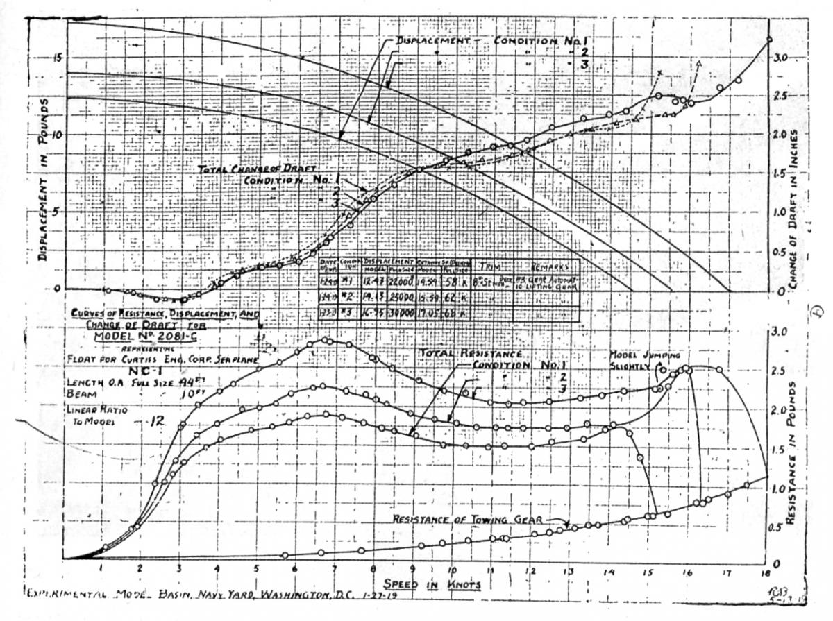
In determining the characteristics of the hull for a flying boat, a model is made to scale and is tested in the model basin or towing tank in a manner similar to that used in the testing of models of ships. The accompanying curves show the results of the model basin tests of the NC hull under three conditions of loading. These curves are self-explanatory.
The NC type of hull, with the tail surfaces carried on outriggers supported in part from the upper rear wing beam and in part
from the hull stern post, was suggested by Mr. Curtiss in his original proposal. The details of the hull design are largely the work of Commander H. C. Richardson, of the Construction Corps. Commander Richardson had had a very wide experience in the design and testing of pontoons for seaplanes, and, as a result of this experience, was best qualified to take up the design of a new hull of the type to be used for the NC flying boat. As the result of his experience in the design and testing of pontoons, he decided
that a very satisfactory float could be produced by modifying the design of the R-6 pontoon which had proved very successful in its use in seaplanes. Accordingly, the general dimensions of the hull were determined by increasing the dimensions of the R-6 pontoon in the ratio of the cube root of the displacements. The shape of the V-bottom is similar to that of the Curtiss H-16 flying boat, and to the British F-5, which was later adopted by the U. S. Navy. Changes were made in the shape of the deck of the pontoon, at the bow, to allow for a gunner’s cockpit, and the stern was changed to allow for the stresses produced due to the weight of the tail surfaces to be supported from the stern of the hull.
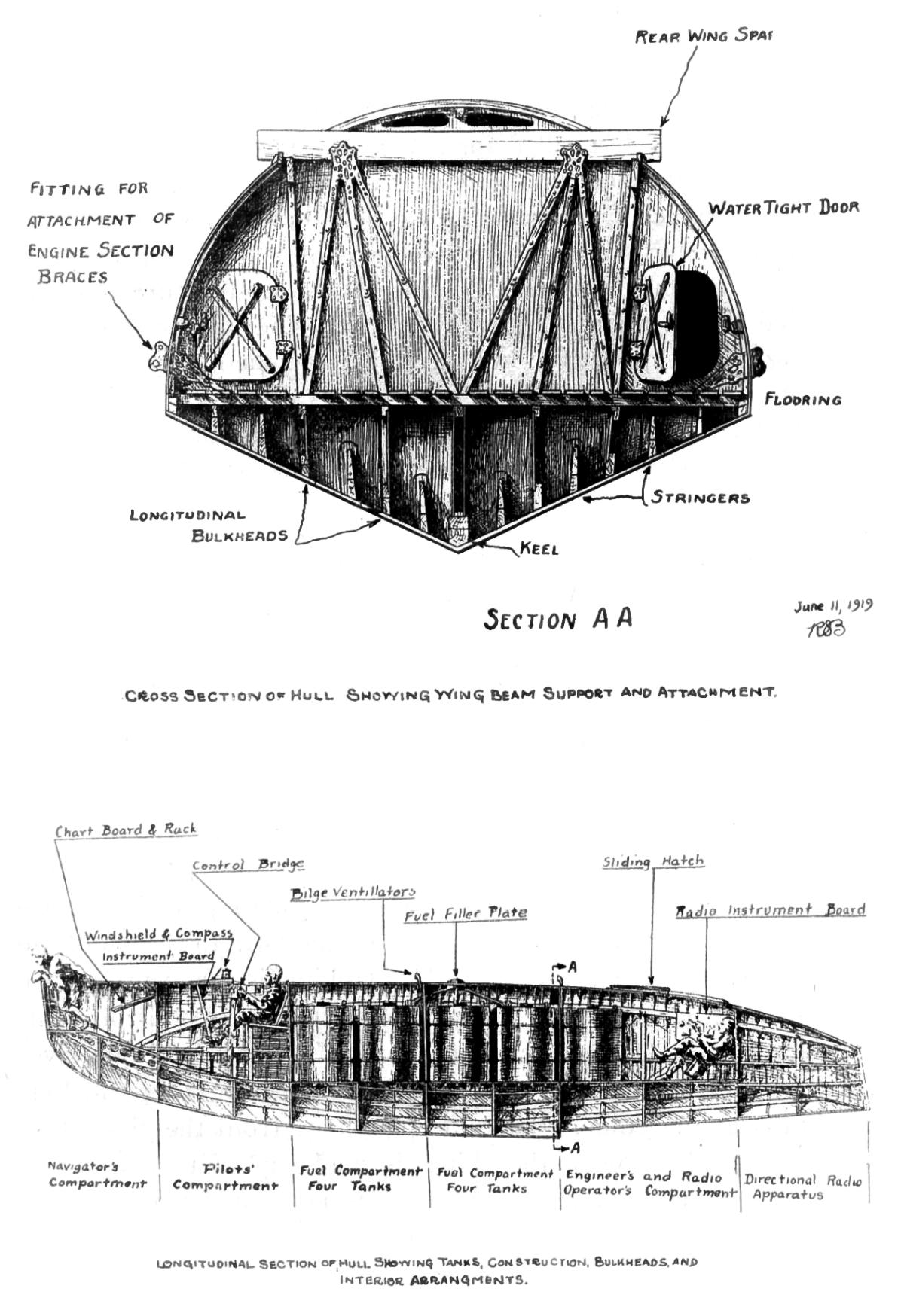
To provide for the heavy weights to be carried in the hull, for which no provision was made in the design of the R-6 pontoon, the internal construction was very different from that of the pontoon. The design called for sufficient strength for 10,000 lbs. of gasoline in the hull, in addition to the weights of the crew and spare parts which would also be carried there. To provide this necessary strength a fuselage structure of ash and spruce was the basis of construction. To this fuselage structure suitably designed floors, floor stringers, keels and side keelsons, and the framework to support the hull deck, are attached. By means of five 2-ply mahogany bulkheads, the hull is divided into six compartments. Access from one compartment to another is had through watertight bulkhead doors. At the points where the wing beams are attached, these bulkheads are suitably braced with spruce strips and steel straps so that the weight of the hull is distributed throughout the bulkheads and to the wing beams without producing excessive strain on any one part of the structure.
The bottom planking of the hull is Spanish cedar, made up in two layers with a layer of batiste and marine glue between. To provide for the pounding of the hull bottom, and to give the required strength with a minimum weight, the bottom planking is made up in various thicknesses ranging from a minimum of 1/8 inch to a maximum of ¼ inch. From the bow to a point eight feet aft of the bow and from the step to the stern, the planking is made up of one layer of 1/8 inch and one layer of 3/16 inch Spanish cedar. From the point eight feet aft of the bow to the bulkhead under the forward wing beam, the planking is made up of two layers of Spanish cedar, inch in thickness. From this bulkhead to the step, there is one layer of 3/16 inch and one layer of ¼ inch Spanish cedar, the outer layer tapering to inch in thickness at the chine. Tile side planking, from the chine to a point 15½ inches above the chine, is made up of two layers of 1/8 inch mahogany planking. From this point upward, the deck covering is one layer of 3/32 inch white cedar, covered by light cotton duck, glued to the planking with water-proof glue. In one of the hulls this planking is of thin 3-ply veneer and the duck covering is not used.
As in the design of the other portions of the machine, weight estimates were made as soon as the design had progressed to the point where this was possible. The estimated weight of the hull was found to be considerably in excess of the weight allowed, and it was therefore necessary to make a reduction in this weight. Commander Richardson took this up and, as a result of his experience in design, reduced the sizes of all parts to those he considered as the minimum allowable. Upon a recalculation it was found that the estimated weight came within the figure allowed for hull weight. It is interesting to note at this point that the weights of the four hulls as constructed, all exceed the estimated weight of about 2400 lbs. by amounts varying from 100 lbs. to 300 lbs.
To prevent the wing panels coming in contact with the water during taxiing, or when the machine is moored in the water, it is necessary to provide wing tip pontoons. Design of such pontoons is similar in many respects to the design of the hull. They must be especially rugged in their construction because of the great possibility of their being damaged during a bad landing or during landing in a rough sea. They must have a considerable displacement to prevent the wing tips being submerged when the machine is rolling badly on a rough sea. With the original wing tip pontoon, when the pontoon is completely submerged and the wing tip is about to touch the water, the righting moment is 2.65 times the tipping moment due to the weight of 22,000 lbs. With a load of 29,000 lbs., the righting moment would be double the tipping moment. The size of the pontoon was later increased and the shape changed to overcome the tendency to nose under during taxiing on rough water, with the consequent subjecting of the wing beams and pontoon struts to very sudden and severe strains.
There are two methods that may be used in determining the areas. To be used in the construction of the tail surfaces. One of these is an analytical method which makes use of an equation derived from the consideration of many machines which have been in satisfactory practical use. This equation may be written a =.51 AC/L, where a represents the combined area of the horizontal stabilizer and elevators, A represents the total wing area, C represents the wing chord and L represents the distance between the mean centers of pressure of the wing panels and the tail surfaces. The use of this equation will give an approximate value of the necessary horizontal control areas, which is then apportioned to stabilizer and elevator in the ratio of 1.2 to 1. It is wise, however, to construct a model of the complete machine and to determine the effectiveness of the tail surfaces by a test of the model in the wind tunnel, which constitutes the second method of determination as noted above. This method is the one which should be used as a check in all cases, as it shows very definitely the operating characteristics of the machine. If these characteristics are not quite satisfactory, changes in the size and shape of these control surfaces may be made and tests may be repeated until a satisfactory arrangement is obtained. It is customary in design to make the span of the horizontal stabilizer approximately one quarter of the total wing span and to make the distance between the mean centers of pressure, as noted above, equal to approximately three times the wing chord. With these relations as a basis of the design, it is possible to determine the approximate areas for the control surfaces, and then by means of a wind tunnel test to determine the exact area required.
The analytical method described above was applied to the design of the stabilizer and elevator for the NC boat. A model made to exact scale was then tested in the wind tunnel, and the tail surfaces were found to be entirely too small. A series of tests was then carried on with stabilizers and elevators of various sizes and shapes to determine the construction which would provide for most satisfactory operation. It is interesting to note that the actual area determined upon would have called for the use in the above equation of a constant of .68 instead of .51.
This increase of area was necessary because of the shape of the hull and of the method of support of the tail on outriggers at a distance of approximately 20 feet aft of the hull stern post. With the usual design of boat hulls the long, practically flat, hull bottom provides a considerable stabilizing surface, which is entirely absent in this construction. To make up for this decrease in hull surface, additional area must be provided in the horizontal stabilizer. This is true also of the vertical stabilizers, which were of a larger proportional area than is used on the conventional type of flying boat.
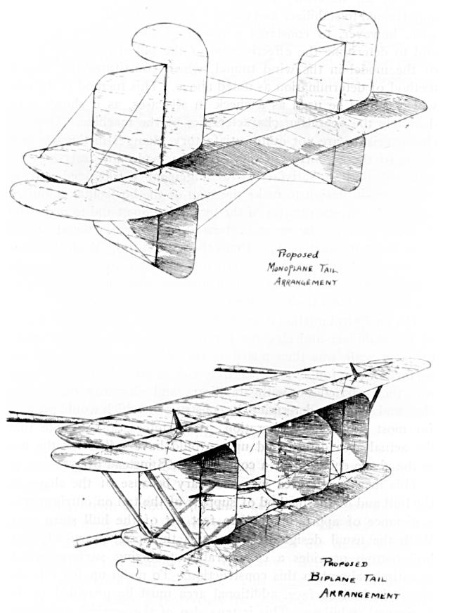
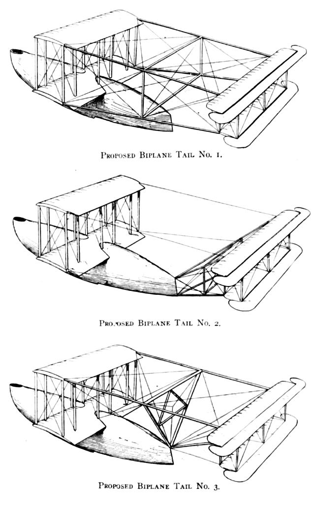
In determining upon the type of tail surfaces to be used for this design, four important factors were considered. These were, first, the weight of the total structure; second, the stresses set up in structural members other than those used directly in the support of the tail; third, the rigidity of the complete structure; and fourth, the possibilities of destroying any single member without the destroying of the entire structure.
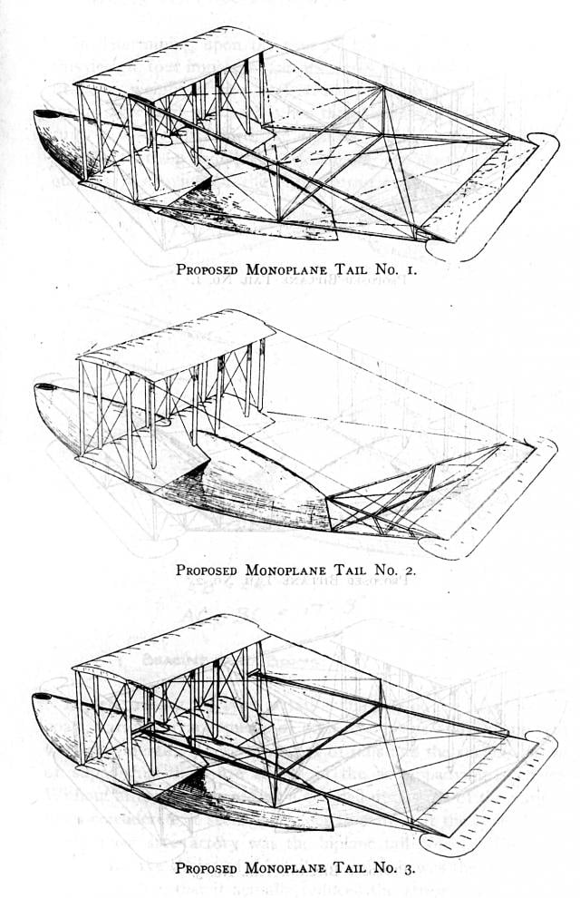
In determining the type of tail surface to be used for the NC boats, various arrangements of both monoplane and biplane tails were considered. These two types of tails and the various means of supporting them are shown in the accompanying sketches. Without attempting to go into a detailed discussion of the various types considered, it seems sufficient to state that the type chosen as the most satisfactory was the biplane tail No. 3. The main reasons for the choice of this tail were that it was the most, rigid in construction, that it actually reduced the stresses in the wing beams instead of increasing these stresses, and that there was less possibility of failure of the entire structure due to a failure of any one of the supporting wires or cables. The actual weight of the structure is somewhat greater than the estimated weights of some of the other arrangements, but this factor is thought to be less important than the other three mentioned above.
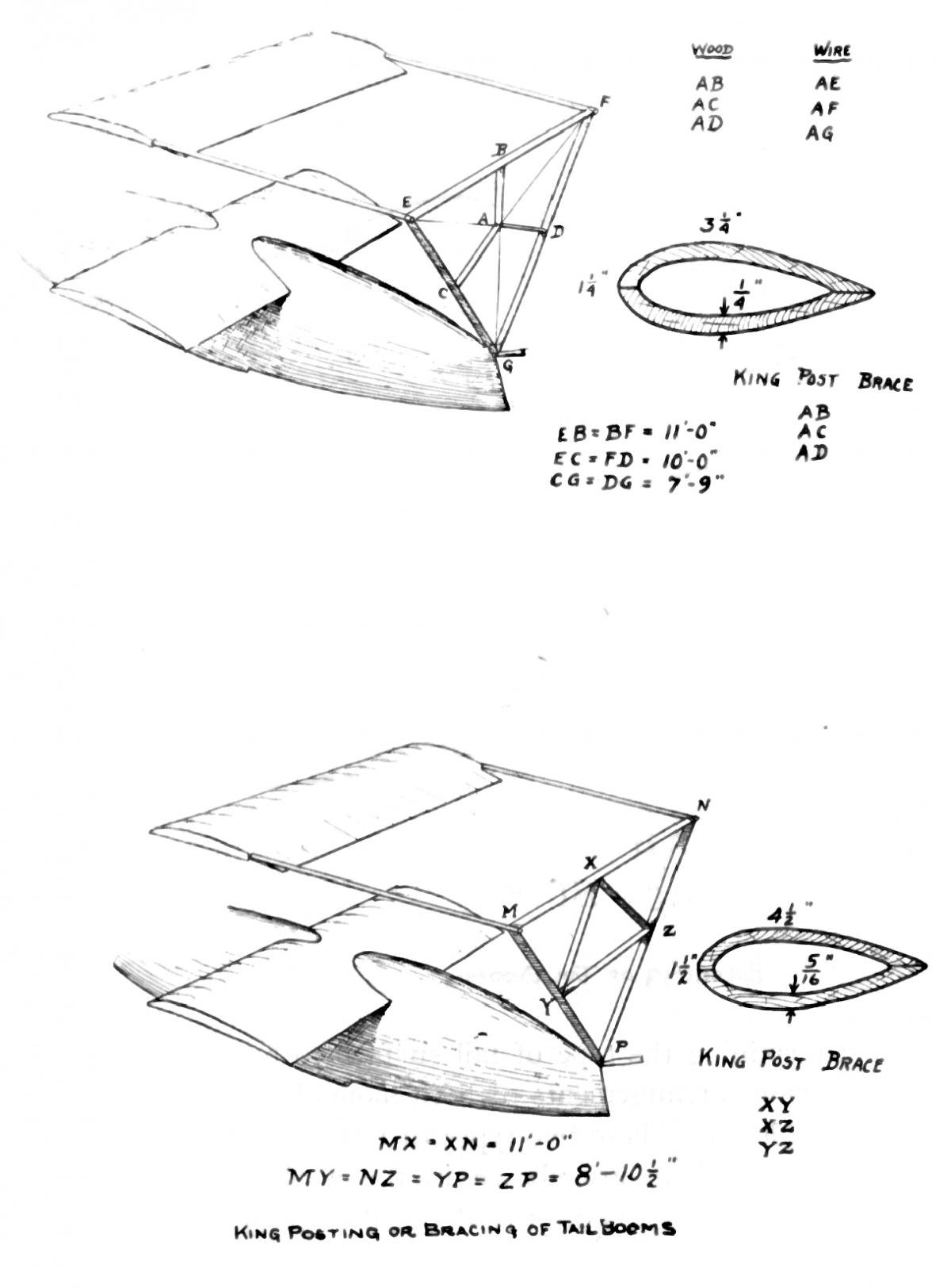
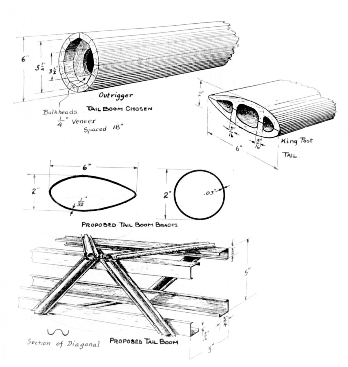
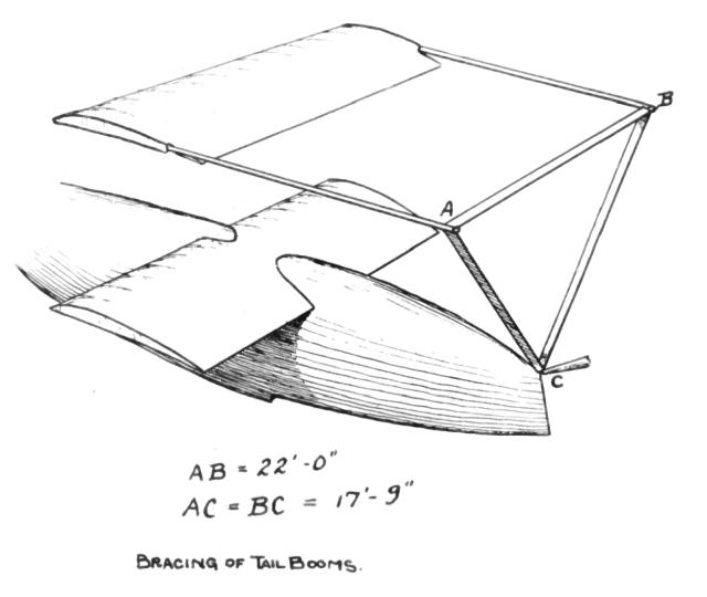
In the investigation of methods of support of the tail, outriggers built of aluminum, steel, and spruce were compared. The various sections considered are shown in the accompanying sketches. Here again, for practically the same reasons as have been outlined above in connection with the discussion of wing struts and wing beams, the spruce seemed to promise the most satisfactory conditions for construction and for use, and, therefore, this material was chosen.
Before this design was entirely detailed, a model of the complete plane was tested at the Washington Navy Yard wind tunnel. A similar model was made later and tested in the wind tunnel of the Curtiss Engineering Corporation. The curves giving the results of one of the wind tunnel tests are shown in the accompanying figure. The tests were made to determine the lift and drag of the complete machine, and its longitudinal stability. The curves for lift and drag are shown corrected so as to give the coefficients in terms of pounds per mile per hour squared for the full-size machine. The curves showing the relation between the required horsepower and speed are derived from the lift and drag curves. These curves represent the operating characteristics of the machine for a total load of 20,000 lbs. and are used simply to illustrate the results of a wind tunnel test, and not to show the exact operating characteristics of the NC type of seaplane. In the chart showing the longitudinal stability, the condition of stability is shown by the position and direction of the vectors. If the vectors are grouped uniformly fore and aft of the center of gravity of the machine, and not too widely spaced, good conditions of longitudinal stability are indicated. If the vectors are too widely spaced, it shows the machine as too stable. If they are grouped mainly forward of the center of gravity, it indicates a condition of tail heaviness, and if grouped too far aft of the center of gravity, one of nose heaviness. If the condition of tail heaviness or nose heaviness is not excessive, it can be corrected by a change in the position of the elevators; if it is excessive, it requires a change in the design of the horizontal stabilizer or a change of its angularity with respect to the wing panels.
The conditions as outlined above are those which it was necessary to meet in the design of this type of machine. To have direct charge of the design, which, for the Bureau of Construction and Repair, was under the general supervision of the writer, the Curtiss Engineering Corporation detailed Mr. W. L. Gilmore, their assistant manager, Mr. S. V. Davis, who had charge of their drafting room, and Mr. J. A. Christen, who was in charge of the drafting force which was working particularly upon the design of the NC parts. Working with these men and looking after all information regarding changes in design, the strength of parts, and the effect upon the strength of various parts of changes in the design, was Ensign C. J. McCarthy. The design work was started at the plant of the Curtiss Engineering Corporation in Buffalo, and in December, 1917, was removed to the new plant of this corporation which had just been completed at Garden City, L. I. It is interesting to note in connection with this removal that all those engaged upon this design work completed their work in Buffalo at the usual time in the afternoon, were carried to Garden City on a special train at night, and reported for work at the Garden City plant on the following morning, without any loss of time on the design work.
The design, because of the immense amount of detail involved, seemed to progress very slowly and it was not until January 19, 1918, that it was finished sufficiently to begin the building work of the machines. For this construction work a contract was made with the Curtiss Engineering Corporation for four complete seaplanes. For these craft, the Navy Department was to supply three of the hulls, and all the engines. The fourth hull was to be built by the Curtiss Engineering Corporation. A contract was let on the basis of actual cost plus 10 per cent for profit.
To facilitate construction, various parts were made under subcontracts from the Curtiss Company. The principal ones which may be noted are as follows. Wing panels, control surfaces, and wing struts, were built by Locke & Company of New York City, expert manufacturers of high-class motor car bodies. Metal parts were made by Unger Brothers, Newark, N. J., manufacturers of silverware, jewelry and all kinds of metal articles ordinarily handled by jewelers. Later, to expedite the production of metal parts, some of these were manufactured by the Beaver Machine Works of Newark, and some by Brewster and Company of New York City. Wing tip floats were built by the Albany Boat Company, builders of high-class steam launches and motor boats. These, later were replaced by larger floats built by the Naval Aircraft factory of Philadelphia. The outriggers supporting the tail were built by the Pigeon-Fraser Hollow Spar Company of Boston, makers of masts and spars for racing yachts. The gasoline tanks were built by the Aluminum Company of America of Pittsburgh. The construction of these tanks was the largest and most difficult job of this nature ever undertaken by any aluminum manufacturer. Two of the hulls to be supplied by the navy were built by Lawley & Sons of Neponsit, Mass., and one by the Herreshoff Manufacturing Company of Bristol, R. I. These hulls were built on the basis of cost, plus 10 per cent profit on an estimated cost, with the understanding, if the cost could be reduced below the estimated cost, the contractor would be paid 10 per cent on the estimated cost, and, in addition, 25 per cent of the difference between the actual and the estimated costs.
To assist the Curtiss Company in expediting the production of these parts, and to aid in every way in the construction and assembly of the machine, four officers attached to the office of the writer, were detailed to work with Mr. Gilmore of the Curtiss Engineering Corporation, who had been placed in full charge of the construction work on these four machines. Only because of the faithful work of these officers was it possible to complete the first of these flying boats in September, 1918.
This boat, known as the NC-1, had a power plant which consisted of three low compression direct drive liberty engines, arranged to drive tractor propellers. This arrangement was chosen because of the necessity of keeping the weights of the motors forward to bring the center of gravity in the required position with respect to the center of lift. After actual tests of the machine it was found that slight variations in the position of the center of gravity had practically no effect upon its operating characteristics, and it was decided to change the arrangement on the third and fourth boats to two tractor motors and one pusher motor. This installation was later decided on for the second boat as well.
The NC-1 was completed and assembled for tests at the Rockaway Beach Naval Air Station in September, 1918. The engines were tried out for the first time on October 1, and the boat was weighed, to determine the total bare weight, on October 2. In weighing this machine, four platform scales of 8000 lbs. capacity each were used. These scales were so placed that jacks resting upon the scale platforms could be placed directly under the engine section wing beams, at the outer strut stations. By jacking up, the entire weight of the machine was transferred to these four points. The summation of the four scale readings gave the weight of the plane. By carefully adjusting the position of the machine, leveling it fore and aft and transversely, the weights as indicated on the scales made possible the calculation of the fore and aft position of the center of gravity. The total weight was 12,740 lbs. This weight did not include any supplies or equipment. It was the net bare weight of the machine itself. The estimated weight for the complete machine as worked out by the Curtiss Engineering Corporation was 11,900 lbs., 840 lbs. or 6.6 per cent less than the actual weight. The center of gravity was 65 inches aft of the leading edge of the lower engine section wing panel, or 28 inches aft of the mean center of lift of the wing panels. This condition indicated very decided tail heaviness, and, in the first trial flight which was made, it was decided to place in the bow of the machine, 15 feet forward of the leading edge of the lower engine section wing panel, a sand load of 1755 lbs., so that with the weights of cooling water, pilots, mechanicians, fuel and oil, the center of gravity would coincide with the center of lift. This would bring the gross weight of the machine in flying condition up to 16,500 lbs.
The first test of the NC-1 was made on October 4, 1918. In this test, though the craft was very tail heavy, its operation as a whole was very satisfactory, and indicated that the work of the designers had been a success. It was found necessary, subsequently, to make slight changes in the position of the horizontal stabilizer to neutralize this tail heavy condition, but, otherwise, no radical changes were necessary in the design or construction.
It might be interesting at this point to note briefly some of the opinions of this craft gathered during the time of its construction. After the hull of the first machine had been completed and preliminary assembly had been partly carried out, Colonel Porte of the Royal Air Force, who had been associated with Mr. Glenn Curtiss in the design of the America, the boat which was built in 1914 for Mr. Rodman Wanamaker, for a trans-Atlantic flight, visited the Curtiss Engineering Plant and looked over the NC-1. At that time, Colonel Porte would make no comment beyond the simple statement, “it is very interesting,” but from statements made by others who had come in contact with Colonel Porte shortly after this visit, it is evident that his opinion of the boat, if it had been stated, would have been far from encouraging. In July, 1918, a British Aviation Commission headed by Major General Brancker and including as a principal technical officer, Colonel Sempill, of the Royal Air Force, also inspected the boat. Colonel Sempill, in a report upon his return to England, commented as follows: “The hull of this machine was examined and is the design of a naval constructor. The machine is impossible and is not likely to be of any use whatever.” Several people of considerable airplane design experience stated frankly their doubts of the ability of the hull to get the craft into the air, and even Mr. Curtiss himself thought the planing surface of the boat hull insufficient. These are only samples of the opinions which were held by many persons of the design of this machine. The gratification of those connected with the design due to the successful operation of the completed plane can be imagined.
The tests made on the NC-1 showed operating characteristics very much better, as regards lifting capacity, and speed in the air, than had been indicated by the wind tunnel tests. With the three low compression tractor engines, it got away with a load of 22,000
lbs. at a speed of 52 miles per hour, after planing approximately one minute. The wind tunnel experiments had indicated a getaway speed of approximately 60 miles per hour and a maximum speed of approximately 72 miles per hour with this load. The actual test showed a maximum speed in still air of approximately 80 miles per hour. Because of this exceptionally good showing, it was decided to install high compression engines to determine what load could be handled in this way. Tests made with high compression engines showed the maximum lifting capacity to be 24,780 lbs., as compared with the original 22,000 lbs. for which the craft was designed. The getaway with this load was made under very unfavorable conditions as to wind and tide, and it is very probable that with more favorable conditions, the three high compression engines would have been able to lift 25,000 lbs.
Because of the possibility which seemed to be indicated, of the machine handling much heavier loads than the 25,000 lbs. just mentioned, it was decided to install an additional engine and make tests to determine the limit of loading of the machine. Accordingly, the NC-2 was equipped with four high compression Liberty engines, arranged one tractor and one pusher in tandem in a nacelle on each side of the center nacelle. The pilots and controls remained in the center nacelle as in the original design. With this arrangement of engines, the machine got away successfully with a load of 28,100 lbs.
There are several objections to the double tandem arrangement of engines described in the preceding paragraph. The efficiency of operation of the two engines in tandem can never be equal to the efficiency of operation if the two engines were set up in separate nacelles; in case of failure of one of the tractor engines, the pusher engine becomes exceedingly inefficient because of the propeller of this engine having been designed to operate
in the slip stream of the tractor engine; and there is an excessive torque on the rudder which would result from an attempt to keep the plane to its course if one or both of the engines in one of the tandem nacelles should fail in operation.
To obviate as far as possible the difficulties just outlined, it was decided to install in the NC-3 and NC-4, four engines arranged with one tractor and one pusher in tandem in the center nacelle, and one tractor engine in a nacelle on each side of the center. This arrangement would provide for a better efficiency of operation and for fewer difficulties in operation due to a breakdown of any one of the engines. Trials made on the NC-3 and NC-4 proved this arrangement very satisfactory and it was adopted for the installation to be used on the trans-Atlantic flight.
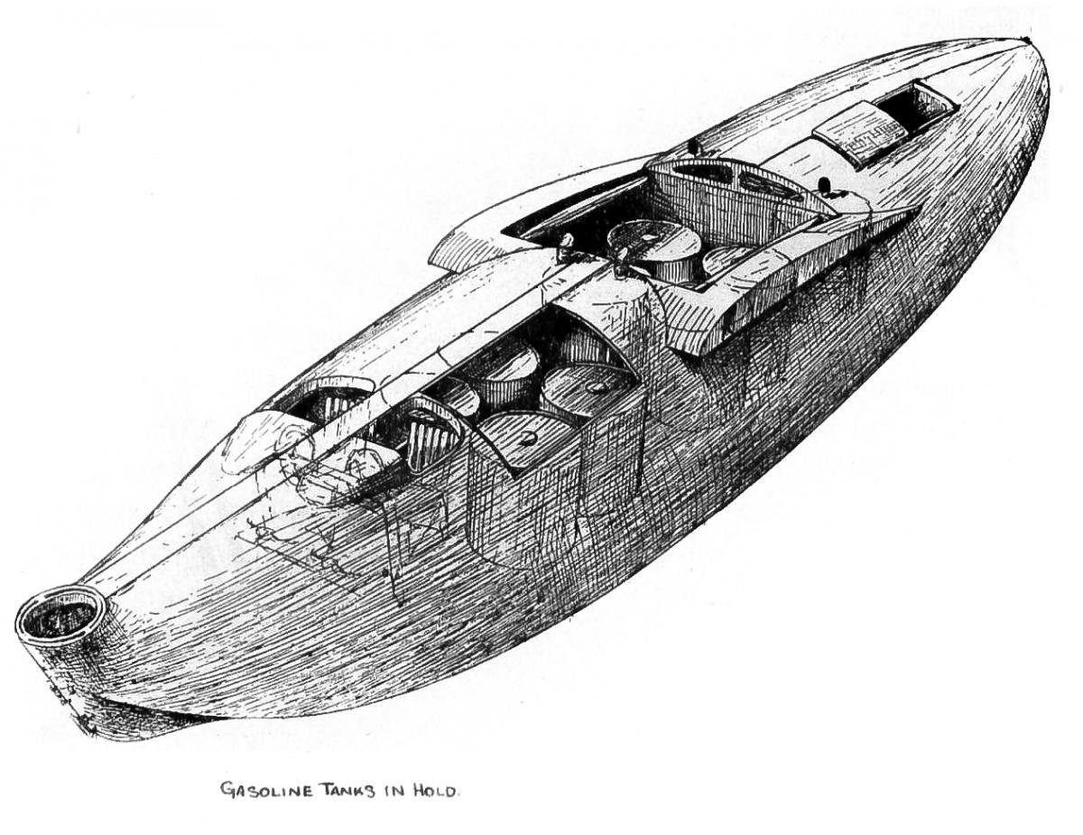
The original design of the NC-1 provided for a total gasoline capacity of 891 gallons. For this gasoline supply, four 200-gallon aluminum tanks were placed in the hull, and a 91-gallon gravity tank was placed in the upper engine section wing panel, directly above the center nacelle. This capacity was later increased by the addition of two 200-gallon gasoline tanks in the hull compartment forward of the main tank department. When the power plant was changed to four motors instead of three a further increase in
gasoline supply was provided for by the addition of two more 200-gallon tanks in the compartment forward of the main tank compartment and one 200-gallon tank in the compartment aft of the main tank compartment. These tanks are all connected by means of aluminum tubing so gasoline may be drawn from all tanks equally. Valves make possible the shutting off of any tank in case of leakage, or the proper adjustment of the center of gravity of the machine, by regulating the gasoline drawn from any tank.
Gasoline is supplied, by means of air driven plunger pumps placed on the hull deck, from the main tanks to a 91-gallon aluminum gravity tank, carried in the center of the upper engine section wing panel as noted previously. This tank is of the same depth as the panel and is designed to have sufficient strength to carry the flying load corresponding to its area. For emergency use, a hand pump is also installed. An overflow line is provided from the gravity tank to the main tanks, and a glass cup connected in this line gives a visible indication of the operation of the pumps. One pump when operating properly, has sufficient capacity to cause a continuous overflow from the gravity tank. Two pumps are provided, and, with the hand pump, insure at all times an adequate supply to the gravity tank.
The gasoline is distributed from the gravity tank to the motors through aluminum tubing, with hand operated brass cut-off valves of the globe type connected in the lines just below the gravity tank. Aluminum cock-valves were used originally, but these were unsatisfactory, due to sticking of the valve. With the cut-off valves open, the supply of gasoline to the carburetor is regulated by the float, the controls for which are located in the pilots’ cockpit. The two outer motors are operated through a differential throttle control, and the center pusher and the center tractor have individual throttle controls.
Lubricating oil for the engines is carried in aluminum oil tanks, supported on extensions of the engine bearers. These tanks have a capacity of 40 gallons for each engine. From results obtained in operation, this capacity is much more than is required for the longest lap of the trans-Atlantic flight, 1300 miles. Indications are that 25 gallons per motor would have been more than adequate for this supply.
Radiators are of the honeycomb type. Plate radiators have been tried in the operation of the craft, but had not proved satisfactory, due to insufficient strength to withstand stresses set up during operation of the plane. With a stronger construction these radiators could be made satisfactory for operation, but it is questionable whether the reduction in head resistance obtained would compensate for the increased weight.
Controls are of the Deperdussin type, so built that two pilots seated side by side can, in case of need in rough air, work together on the operation of the controls. In the pilots’ compartment is an instrument board, electric lighted, carrying an air speed meter, an altimeter, tachometers and spark retards. In the engineers’ compartment in the hull is a second instrument board, with radiator, water and oil thermometers and oil pressure gauges attached. The engineer on watch is held responsible for the satisfactory operation of the engines, and can tell from the readings on the instrument board what changes in conditions are necessary to make the operation satisfactory.
To provide a reserve of cooling water, a 20-gallon auxiliary water tank is carried in the hull. By means of a system of copper piping and a hand pump, water may be supplied to any one of the four radiators. The radiator vent pipes are attached to copper tubes leading back to the auxiliary tank. In this way any vapor or steam formed in the radiators is condensed in the tubes and led back to the supply tank. The only loss of water, therefore, would be due to leakage.
In the engineers’ compartment are located, also, the wireless telegraph and wireless telephone instruments. The former is made up of two sets, one for use in the air with 100-feet antennae trailing downward from the tail support, and with power supplied from an air driven generator, and an auxiliary set for use when on the water, with the antennae carried on the skid fin masts above the upper wing panels, or for emergency in the air, a short trailing antennae. The former set has a radius of 300 miles, and the latter one of 75 miles. The latter set was so arranged that it could be used also for the wireless telephone connections. For communication between members of the crew of a boat, an intercommunicating telephone set was provided. Connections of this set were so arranged that the wireless telephone receiving set could be plugged into the intercommunicating set, and all members of the crew could hear reports coming in by wireless telephone.
In the stern compartment there is installed a wireless direction finding compass. This is an adjustable wireless receiving coil, with an indicator attached. As the position of the coil is changed the intensity of the sound in the wireless receiver changes. When this sound is a maximum, the indicator attached to the movable coil gives the bearing of the sending station.
Such is the story of the design and construction of the NC flying boats. The performance of these machines in the recent trans-Atlantic flight, both in the air and on the water, shows the excellent results that may be obtained by the application of real engineering principles of design to the solution of problems seemingly as impossible of solution as was this one when first proposed by Admiral Taylor.