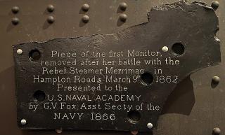
Attached to a wall in Preble Hall at the U.S. Naval Academy Museum in Annapolis, Maryland, is one of the oldest and, for its time, largest artifacts from the USS Monitor. It is not particularly exciting to look upon—although it is humbling to be able to actually touch a piece of this famous ship—but this artifact is the key to picturing a distinctly different image of how the Monitor’s turret actually looked during history’s first battle between ironclads—the Monitor’s clash with the CSS Virginia on 9 March 1862, during the Battle of Hampton Roads. This relic may help prove that the well-known round turret, in fact, had a prominent flat shield attached.
The artifact is made of 1-inch-thick wrought iron, is 32½ inches wide and 20¼ inches high, and appears to be an armor plate from the famous ship. It is inscribed by Gustavus Vasa Fox, Assistant Secretary of the Navy from 1861 to 1866. Fox was very influential in the development of ironclad ships, especially the Monitor type. He became close friends with the Monitor’s inventor, John Ericsson, and witnessed, from the deck of the USS Minnesota, the battle between the Monitor and the Virginia. The inscription on the relic reads:
Piece of the first Monitor, removed after her battle with the Rebel Steamer Merrimac [CSS Virginia] in Hampton Roads March 9th 1862. Presented to the U.S. NAVAL ACADEMY by G.V Fox Asst Secty of the NAVY 1866.1
It is flat, not curved like the wrought iron plating of the turret, and is pierced in six places for bolts or rivets. Weighing about 100 pounds, it has three flat sides, a clearly damaged side—and a cut-out circular area.
There is little need to describe the world-famous Civil War vessel USS Monitor—the so-called “cheesebox on a raft.” Launched in 1862, the U.S. Navy’s response to the Confederate Navy’s conversion of the burnt hulk of the USS Merrimack into the ironclad CSS Virginia, the Monitor represented a revolutionary ship design. Ericsson’s radical new creation, privately funded, was built and launched in just over 100 days.
“Ericsson’s Folly” did not resemble any other ship of the time; at 173 feet long with a 41½-foot beam, 11-foot draft, and about 18 inches of freeboard, she had no observable means to propel herself—no masts, rigging, sails, or paddlewheels—nor means to control her. The deck had two hatches, two removable smokestacks and ventilator covers, one fixed 5 x 4–foot pilothouse protruding about 4 feet above the deck—and, of course, her 9-foot high, 21½-foot diameter, iconic turret.
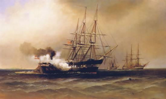
Ericsson’s concept was that, in battle, the only parts visible would be the short pilothouse and the round turret. This is clearly shown in the hundreds of paintings and drawings of the famed battle between the Monitor and the Virginia. There is compelling evidence, however, to suggest that these well-known images are not correct: The round turret was not totally round.
Extra Protection at the Gun Ports?
Ericsson’s early October 1861 specifications for “an Impregnable Floating Battery” are written as a detailed explanation of the proposed vessel, in complete sentences, as if one were describing the vessel to another person. He wrote that the “Wrought Iron Turret, 21½ feet outside diameter, 9 feet high and 8 inches thick is . . . composed of eight thicknesses of best American plate iron each one inch thick, or it may be composed of ¾-inch plates to a thickness of 3¾ inches rivetted [sic] together and covered with plates 4¼ inches thick bolted to the former.”2
Ericsson wrote these two varying descriptions for the turret in this early specification because he was not yet sure exactly how it would be made. He was assuredly aware of the extensive testing the British Admiralty had completed on naval armor. By 1861, its Special Committee on Iron stated that “Laminated armor . . . proved ‘in every case far weaker than solid plates of similar thickness.’”3 Also, the committee’s tests proved that 4½-inch wrought-iron plates could resist French 50-pounders and British 68-pounders. In fact, no shell succeeded in penetrating these plates until the September 1862 tests of a Whitworth 12-inch rifled gun.4
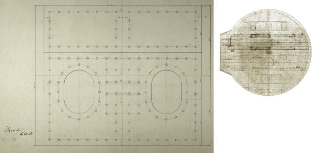
while the one on the right shows how it would have looked originally, with its “Turret Shield” still in place.
(It evidently was removed in the weeks after the battle).Courtesy of the Author
The U.S. Navy also had done extensive testing of its naval guns, leading to the production in 1855 of the widely respected Dahlgren “soda bottle” design. However, it would not be until 20 March 1862 (11 days after the Battle of Hampton Roads) that Commander John Dahlgren, after years of lobbying, finally received permission to test his naval guns against actual armor targets.5
Ericsson knew the state of the art in armor in 1861, and he fully intended to use 4-inch-thick iron plates on the outer layer to make his ship and turret “impregnable.”6 He also knew what iron was available as well as his time constraints, since he guaranteed his floating battery would be launched in 100 days. He first believed that even 4-inch wrought-iron plate was not available in the United States, and that 4½-inch iron plate would need to be imported from England.
He subsequently learned that Horace Abbot and Sons of Baltimore could roll the 4-inch plates, but it would take two months to set up the mill to do this.7 Since neither of these solutions was satisfactory, Ericsson soon realized his only option was to construct the turret of eight 1-inch iron plates.
Most contemporary and later descriptions jibe with the actual turret as recovered from the seafloor by the National Oceanic and Atmospheric Administration in 2002. As recovered, it is composed of eight 1-inch-thick iron plates. The innermost two are riveted together; the outer six are bolted to these with overlapping joints. (There is also a thin ¼-inch iron “nut guard” or “mantlet” inside the innermost plates, which covers the nuts of the bolts holding the turret together.8 This provides no additional armor; it was intended to protect the turret crew if a bolt sheared off during battle.)
However, a number of contemporary accounts report that the thickness of the turret at the gun ports was greater than 8 inches.
‘On Side . . . Most Exposed . . . Additional Shield’
In November 1861, Scientific American reported extensively on the construction of the Monitor, aka the Ericsson Battery, stating, “We have had an opportunity of making a minute examination of the plans of this novel instrument of aggressive naval warfare.”9 At that time, it reported that “Ericsson proposes to dispense with two of the outer plate rings of the turret, and to attach in their place staves of rolled iron 4 inches thick, thus presenting an aggregate thickness of 10 inches of plating.”10
In a later edition in March 1862, the magazine reported: “Upon the sides of the turret that has the [gun] port holes, through which the guns are discharged, the thickness is increased by an additional plating 3 inches in thickness; making the sides of the turret which will be presented to the enemy 11 inches.”11
Harper’s Weekly on 22 March 1862 gave a description of the Monitor, taken from the New York World newspaper, which reported: “On the side in which the [gun] port-holes are bored, which will most be exposed to fire, will be an additional shield of 2 inches of iron, making the whole thickness 11 inches.”12
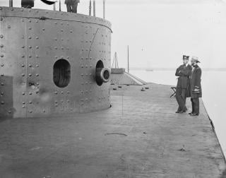
This practical concern for the thickness of the armor at the gun ports “presented to the enemy” and “which will most be exposed” was borne out in the battle with the Virginia. The turret was struck nine times during the battle, at least five of these being near the gun ports, as can be seen in the photographs of the ship and turret from July 1862.13 These images clearly show the oval gun ports and the round turret. In fact, these are so clear that the eight layers of one-inch iron plates can be easily observed and counted in the gun ports.
So, were the contemporary accounts wrong about the thickness of the turret, and where did the battle-damaged iron armor plate from the Monitor on display at the Naval Academy Museum come from? One clue is the description of the “shield” in the report from the New York World—describing the extra layer of thickness at the gun ports.
‘Battery, Shield for Turret’
In Captain Ernest W. Peterkin’s classic reference book Drawings of the U.S.S. Monitor, listing all 207 known engineering drawings of the ship, there is only one reference to a “shield.”14 It is Catalog No. 182, titled in the drawing as “Battery, Shield for Turret” and signed in ink “C. W. M.” (Charles W. MacCord was Ericsson’s chief draftsman).15 This shield was designed to be made of two thicknesses of 1-inch iron plate, with an overall dimension of 8 feet in height and 10 feet in width—and bored out in two places to exactly match the size and spacing of the Monitor’s gun ports.16
In his description of this item, Peterkin notes that he feels that it was never actually used, “as it never appears in any photograph or artist’s conception of the Monitor and does not appear to be present in the wreck.”17 He does note that these dimensions “coincide very nearly with the sketches of the ‘smoke box’ indicated in Catalog Drawing 164.”18
While Drawing 164 in Peterkin’s book is listed as “Turret Details; Roof, Floor Beams, Hatches, Gun Slides, Pendulum Bearings, Bulkhead Armor and Smoke Box,” this title was apparently given to it by Peterkin. The actual title in the original drawing itself is “‘Monitor’/Turret Details,” and this title was written in ink and signed by Ericsson himself.19
This drawing has many excellent details of the turret in ink and working calculations in pencil. It is estimated to have been drawn in October 1861. The “smoke box” is a flat, 10-foot wide, 2-inch thick armor apparatus attached to the turret 12 inches in front of the gun ports. However, nowhere in the drawing is it labeled as a “smoke box.” There is every reason to believe that this “smoke box” was in fact the “Shield for Turret.” Also, it is signed by Ericsson, and he would not have signed off on this unless it was at least part of his plan. It also explains the contemporary accounts, which stated he planned on additional iron armor at the gun ports.
The iron artifact on display at the Naval Academy Museum closely matches MacCord and Ericsson’s drawings as part of the “Shield for Turret.” While the bolt or rivet holes do not exactly match the drawing, their relative positions are very similar in both spacing and symmetry. The size of these holes is identical to the size of the bolt holes in the turret itself—and the circular bored-out area is an exact match for the gun ports.
Also, there is no other part of the Monitor of a comparable size and shape to this artifact, except the “Shield for Turret.” None of the hatches, cabin skylights, coal scuttles, or any other part of the ship is similar to it.
If this artifact is part of the “Turret Shield” and it was on the turret during the battle with the CSS Virginia, as stated—and eyewitnessed—by G. V. Fox, is there other evidence to substantiate this proposition?
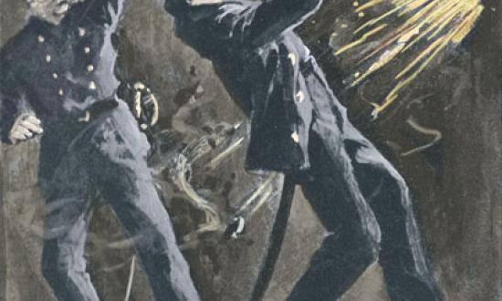
On the day of the battle, 9 March 1862, Chief Engineer Alban C. Stimers, who was instrumental in the Monitor’s construction and served in the turret during the engagement, wrote to Ericsson reporting on the battle and his impression of the ship. He wrote, in part, “The turret is a splendid structure. I do not think much of the shield, but the pendulums are fine things.”20
Also, in the draft log of the Monitor in the National Archives, an entry for 21 March 1862 states: “From Meridian to 4 P.M. fine and pleasant weather,—light wind from E.S.E. and hauling to the S. At 2.30 the tugboat Young America came alongside and took on shore the shield of the turret.”21
Unfortunately, the log of the Young America for this time period is missing from the National Archives, so there is no information on exactly where the tug took the shield.
A Detail Forgotten by History
So, Ericsson indicates that he planned for a “turret shield.” Stimers writes that he “did not think much of the ‘shield.’” The log reports when the “shield of the turret” was taken off the Monitor. And Fox sent what appears to be a part of this “shield” to the Naval Academy. Thus, there is compelling evidence to support that this flat shield was in place in front of the Monitor’s gun ports during the epic Battle of Hampton Roads.
Also, if the horizonal artifact on display is rotated 90 degrees counterclockwise, making it vertical, the gun port boring in it lines up with the starboard gun port of the turret, and the battle-damaged area on it coincides with the major battle damage on the turret itself.
Why hasn’t this been proposed before? One reason is that it is well known Ericsson did not like failure and distanced himself from it, disavowing it, if possible.22 The “turret shield” was an innovative idea, but a failed one. After Ericsson signed his name to it on the “Turret Detail” plan, neither Ericsson nor his biographer ever mention it again. And if not for this artifact Fox sent to the Naval Academy, there would be no solid evidence of a shield at all. Also, as noted, there are only a very few references to this turret shield, and nothing in the log or the records as to who ordered or approved its removal.
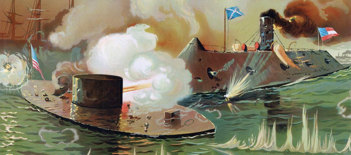
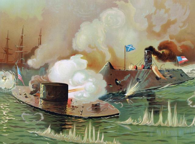
The paintings of the world’s first battle between ironclads will not change, nor should they. The simple, beautiful (in her own way) image of the Monitor does lose some of her charm when seen with the shield in place on the turret. In all probability, however, this is exactly what the gunners of the CSS Virginia saw when they faced off against the USS Monitor on that historic day.
1. The artifact’s museum catalogue number is 1866.001.
2. John Ericsson, “Specifications of an Impregnable Floating Battery, composed of Iron and Wood, Complete Ready for Service Excepting Guns, Ammunition and Stores,” National Archives and Records Service (NARA), subject file, “1775–1910,” ser. AD, ”Design & General Characteristics, U.S. Ships,” box 49, folder 1.
3. James Phinney Baxter III, The Introduction of the Ironclad Warship (Cambridge, MA: Harvard University Press, 1933), 202–3. See also: “Iron Sides and Big Guns—Experiments,” Scientific American 5, no. 21 (23 November 23 1861): 323.
4. Baxter, Introduction of the Ironclad Warship, 205.
5. CAPT Andrew A. Harwood to Dahlgren, 20 March 1862, NARA, RG 75, Box 4, Entry 6, cited in Robert J. Schneller Jr., “The Battle of Hampton Roads, Origins of Ordnance Testing against Armor, and U.S. Navy Ordnance Development during the American Civil War,” Naval History and Heritage Command, www.history.navy.mil/content/dam/nhhc/browse-by-topic/War%20and%20Conflict/civil-war/The_Battle_of_Hampton_Roads.pdf.
6. Ericsson to Smith, 4 October 1861, National Archives, RG 71 Records of the Office of the Chief of the Bureau, Bureau of Yards and Docks, Old Army and Navy.
7. Stephen C. Thompson, “The Design and Construction of the USS Monitor,” Warship International 27, no. 3 (1990): 225.
8. Elsa Sangouard, “News from the ‘Cheese box’ part of the raft,” 16 June 2016, the Mariners’ Museum and Park, www.mariners museum.org/2016/06/news-cheese-box-part-raft/.
9. “The Ericsson Battery,” Scientific American 5, no. 21 (23 November 1861): 331.
10. “The Ericsson Battery.”
11. “The Steam Battery ‘Monitor,’” Scientific American 6, no. 12 (22 March 1862): 1.
12. “The Naval Combat in the Chesapeake: The Ericsson Steamer ‘Monitor,’” Harper’s Weekly, 22 March 1862, 183.
13. U.S. War Department, Official Records of the Union and Confederate Navies in the War of the Rebellion (Washington, DC: Government Printing Office, 1895–1929), ser. 1, vol. 7, 26. Hereafter cited as “ORN.”
14. CAPT Ernest W. Peterkin, USNR (Ret.), Drawings of the U.S.S Monitor, USS Monitor Historical Report Series, vol. 1, no. 1, 1985 (Washington, DC: U.S. Department of Commerce, NOAA, 1985).
15. Peterkin, Drawings, 493.
16. Peterkin, 493.
17. Peterkin, 494.
18. Peterkin, 494.
19. John Ericsson, “Turret Details,” Stevens Institute of Technology Library Special Collections, USS Monitor Drawings—SCW.015, Folder 5, Drawing 57 A and B (1861).
20. Stimers to Ericsson, March 9, 1862, ORN, ser. 1, vol. 7, 26.
21. Log of the USS Monitor, 21 March 1862, NARA, RG 45, Naval Records Collection of the Office of Naval Records and Library, Washington, DC. See also: catalog.archives.gov/id/148768897?objectPage=93.
22. William Conant Church (ed.), The Life of John Ericsson (New York: Charles Scribner’s Sons, 1891), vol. II, 308.


