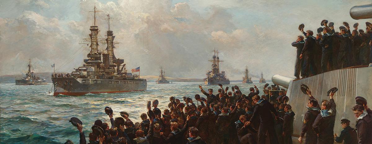
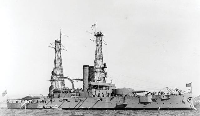
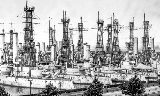
For three decades from about 1910 to 1940, the core ships of the U.S. Fleet were instantly recognizable worldwide even before they were fully visible over the horizon. The U.S. Navy was virtually the sole user of hyperboloid lattice shell structures known within the service as cage masts. In all, 47 battleships and 10 armored cruisers were equipped with the graceful fire-control towers, which also were less commonly referred to as lattice or basket masts. Only six foreign navy battleships mounted them; however, each had a caveat: Two carried ersatz cages, two were American-built ships, and the other two were former U.S. Navy battleships.
The genesis of the design lay with Russian engineer and architect Vladimir G. Shukhov in the mid-1890s. The decade before, he had begun investigating minimizing the amount of materials, time, and labor required for the construction of roofs. This led to his invention of structurally and spatially innovative systems based on doubly curved surfaces known as hyperboloids of revolution and hyperbolic paraboloids.
Despite their aesthetic curves, such designs are constructed of completely straight elements and feature ease of construction, light weight, strength, and spaciousness. Shukhov’s first public display of the concept was a 120-foot-tall tower built in 1896 for a Russian industrial and art exhibition. It still exists.
Although visually complex, cage masts are very simple in concept. Connect two centered rings with equal length straight rods and rotate one of the rings about the central axis. Do the same thing with another set of rings and rods but rotate the same ring an equal number of degrees in the opposite direction, and then combine the results. Changing the lengths of the rods, degrees of rotation, and the diameter of the circles alters the shape of the resulting curves.
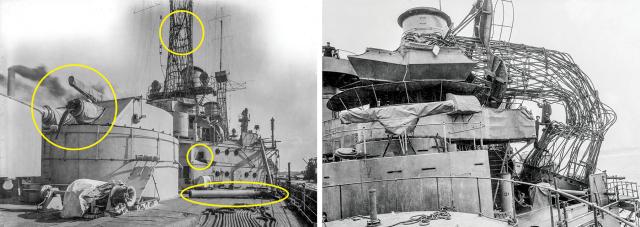
The U.S. Navy cage masts used 90-degree rotation and, instead of rods, 24 sets of seamless drawn steel tubing. At their intersections, they were connected by rings of similar tubing that acted as braces and provided an even strain distribution on the tubing. The limiting factor for mast height was set by the need for access to the Brooklyn Navy Yard, which meant being able to negotiate the 135-foot clearance of the Brooklyn Bridge at high tide. Thus, the masts were set for 120 feet off the waterline. Because the heights of the decks on which the masts were stepped varied by class, the lengths of the tubes also varied.
In general, the average tower was 90 feet tall. Base diameters ranged from 20 to 26 feet, again depending on the mast height, but their top diameters were standard at 9 feet, 6 inches. Atop this was a 10- by-10-foot platform for observers and electrical and mechanical devices used to communicate below.1
Evolution of Masts
For an evolving set of reasons, masts have been required in ships from time immemorial. Initially, they were to support the sails for motive power. Simultaneously, they became a source of better information for the ship’s command by providing locations for observers and supports for signal yards. As steam replaced sail, spar masts at first were generally retained, but they evolved into conical military masts, which featured a fighting top with guns and signaling equipment. As ships’ primary weapons improved with increased gun caliber and range, the need for better observation and control of the shot became obvious. The introduction of radio on board ships necessitated high, widely spread anchor points for antennas. The need for additional height while bearing the increasing weight and volume of observation equipment and its operators eventually surpassed the capability of military masts.
At the end of the 19th century, the maximum battle range for ships was considered to be 4,000 to 5,000 yards. Barely a decade later, that range had doubled, and by the 1916 Battle of Jutland, it had doubled again to 20,000 yards. The days of masts being simple observation posts were long gone.
By the early 1900s, progressive officers, especially later-Admirals William S. Sims and Bradley A. Fiske, influenced by British Rear Admiral Percy M. Scott, began work to improve naval gunnery. With the institution of realistic target practice, they quickly discovered it was impossible to spot the fall of shot at increased battle ranges and equally difficult to plot course, speed, and bearing of enemy ships during evasive high-speed maneuvering. These revelations led to two significant changes in the Navy’s approach to gunnery—salvo firing and director control.
With salvo fire, a number of guns of the same caliber were fired simultaneously to blanket the target with steel and explosives, which also made the fall of the shot easier to determine. Director fire control was a centralized combination of the means for plotting gunnery variables, determining a solution, transmitting that information to the guns for their aiming, and the simultaneous firing of the guns from one location by one officer.
The revolution sparked by the launching of HMS Dreadnought in 1906 coalesced these ideas into one package. The days of battleships armed with multicaliber heavy guns—such as the Connecticut (Battleship No. 18), commissioned the same year with 12-, 8-, and 7-inch weapons—were over.
To function at the ever-increasing battle ranges, a mast’s upper platform had to be high enough above the waterline for a spotter to see the horizon 12,000 yards away. It also had to support very sophisticated and delicate optical equipment. The mounting had to be rigid enough for undisturbed observation, but also capable of absorbing the shock of the main battery firing and the vibrations that it and the engines running at combat speed produced.
The United States saw the solution in the hyperboloid structures, while the British found their answer in simple tripod masts.
Genesis of the Cage Mast
How the attributes of hyperboloid structures came to be imprinted on the minds of U.S. warship designers has not been well documented. Most sources cite the USS South Carolina (Battleship No. 26), as introducing cage masts.2 The first U.S. dreadnought, she was commissioned on 1 March 1910. But the South Carolina was designed with pole military masts; cages were installed during her construction. Their genesis came a bit earlier.
A letter to the U.S. Naval Institute Proceedings in January 1949 by Richard H. M. Robinson, head of the Design and New Construction Division of the Bureau of Construction and Repair from 1905 to 1913, reveals some of the unusual mast’s history.3 The mast design originated (Robinson provided no dates) in the Design Section when he was in charge. His recollection was that it was the work of three people: P. B. Brill, R. E. Anderson, and himself. Sadly, Robinson does not address its origin or influences.
The trio built a scale model of a cage mast, loaded it with the relative weight a full-scale mast would support, and mounted it on a “contraption” that, by a crank being turned, simulated pitching and rolling. Robinson then asked Commander William S. Sims, Inspector of Target Practice, to examine it. After describing the cage mast’s attributes, Robinson asked “whether such thin tubing would detonate a high explosive shell before the shell passed through the mast, and whether shells or fragments hitting the thin tubing would bend them while cutting them, or would clip them off sharply.”
Sims “unhesitatingly” said the structure would not detonate a shell on the near side and that the tubes would be clipped off. Both statements later proved correct. “I then gave him a pair of wire clippers and asked him to go ahead and shoot.” To Robinson’s recollection, he was able to cut all the elements twice in different areas and a majority of elements in one area, before failure.
There was concern that one well-placed shot to the then-standard pole-like military mast could completely sever it, destroying all communications between the gun directors and the guns. One report stated that tests had shown that at least 46 of the cage tower’s 48 steel tubes would need to be shot away before it would collapse.
Put to the Test
The Bureau of Construction and Repair then built a complete full-size mast and installed it on the monitor USS Florida (Monitor No. 9) in May 1908. Instrumentation was added to measure deflection and vibration under at-sea conditions. What was more unusual, it was mounted on the quarterdeck at a 10-degree angle to exaggerate conditions. The tests proved satisfactory. Robinson’s Proceedings letter then mistakenly states that the mast was subjected to firing trials after being installed on the wreckage of the San Marcos (ex-battleship Texas) in Tangier Sound “about 1909–1910,” and it was proven satisfactory and then adopted. In actuality, the mast was tested almost immediately after the sea trials.
On 27 May near the Chesapeake Bay’s Thimble Shoal Light, the Florida was subjected to an unusual trial for a commissioned warship: She was a manned live-fire target.4 The New York Times reported the next day that she “presented the appearance of a resigned martyr.” She had steam up and a large U.S. flag flying from her stern. The weekly wash was hanging from her bridges and superstructure. “But the most striking point in her appearance was the ‘leaning tower’ on her stern . . . resembling a huge waste paper basket.” Atop the “150-foot tall” structure was a platform on which were two “dummy sailors fashioned from boards” who “bravely” looked down at two others on the main turret.
During morning ordnance tests, 12-inch rounds fired by the USS Arkansas (Monitor No. 7) battered the Florida’s turret, which continued to be worked “with perfect ease.” Testing of the mast began about noon. The Arkansas first fired a 4-inch round at an iron plate target placed at the mast’s base, striking it and cutting one of the mast’s tubes and damaging several others. A second shot from the same gun cut two tubes higher up and on the other side of the mast. A third shot missed. The fourth was an explosive shell aimed at the mast top. It “shook” the mast and tore a number of tubes, but the structure “seemed as stable as ever.”
The fifth and final shot was a solid 12-inch round aimed to hit the tower on its outer rim at the lowest edge of its angled mounting. This “terrific” shot ripped up many of the tubes, but “the mast still stood firm.” A lieutenant climbed to its top and tried to vibrate the structure, which had four tons of weight added to the top to further test the cage’s strength. Despite the weight, damage, and movement, there was no apparent weakness. The Times report concluded, “it may be said that this mast is practically indestructible with shot and shell, and has the still further advantage of weighing less than half the old type solid mast now in use.”
Service in the Fleet
Apparently the Navy agreed and almost immediately began installing cage masts in its major warships. After the Florida tests in 1908, the South Carolina was completed with them in 1910. Perhaps the first non-test ship fitted with the mast was the Idaho (Battleship No. 24). A photograph, with the date 14 September 1908 etched in the emulsion, shows the five-month-old battleship still in the white-and-buff Great White Fleet–style paint scheme with a cage mainmast. A 1912 report in The Iron Age noted that this mast was the Florida test mast after it had been repaired.5 The USS Idaho received a cage foremast in 1910.
The first vessels to receive the new masts were new construction battleships, which only required a contract revision, and the oldest four battleships, which had only one military mast at the fore. Little modification work was required to these ships for the installation of the cages at the main. By the end of 1909, 15 battleships had received cages, and three years later, each of the 33 U.S. battleships from the USS Iowa (Battleship No. 1) to the Arkansas (Battleship No. 33) carried at least one such mast. The only other U.S. ships to mount the masts were the ten armored cruisers of the Pennsylvania (Armored Cruiser No. 4) and Tennessee (Armored Cruiser No. 10) classes. Each of these would receive one stepped at the fore by 1914.
Despite cage masts being installed on at least 25 ships through mid-1912, doubts lingered about their survivability, and in particular the viability of voice tube and telephone communication from the fire direction control team on the top platform to the guns.6 Additional live-fire tests were thus carried out in August 1912 with a cage mounted on the wreck of the San Marcos. These were the “about 1909–1910” trials Robinson referenced. The tests were successful, and installation continued on the remaining ships.
No U.S. battleship or armored cruiser engaged in ship-to-ship combat during World War I, thus their masts were never battle-tested. But the Navy had the opportunity to observe and study the strengths and weaknesses of the Royal Navy’s tripod masts. They neither suffered from high-speed steaming vibration nor were as susceptible to shock from gunfire as cage masts. Further, as the caliber and range of ships’ guns increased, larger and heavier rangefinders and more complex calculating and directing gear were required. The increasingly powerful guns and engines created shock and vibrations beyond those imagined when lattice masts were first introduced.
Almost simultaneously with these observations, the cage foremast of the USS Michigan (Battleship No. 27), the second U.S. dreadnought, suffered a catastrophic failure during a severe gale off Cape Hatteras, North Carolina. On 15 January 1918, as the ship snapped back from a heavy roll, the mast had collapsed at its narrowest point; six men were killed and 13 others injured. An inquiry determined that the mast failed in part for several reasons. After a 20 September 1916 explosion of one of the Michigan’s 12-inch guns severely damaged the structure, it had been heightened with a splice at the point of failure, but the mast had not been adequately repaired. There also was evidence of corrosion, primarily on the mainmast, due to funnel gases. The Connecticut’s mast also showed signs of buckling and corrosion.
Twilight of the Cages
By 1918, British success with the tripod was giving some circles within the U.S. Navy serious doubts about the efficacy of the hyperboloid structures. Even at that, though, the cages were hard to give up, although the focus appears to have shifted to number of masts rather than type. In a 19 May 1918 letter to Secretary of the Navy Josephus Daniels, Rear Admiral Hugh Rodman, commander of Battleship Division Nine, reported the recommendations of Naval Constructor Lewis B. McBride after a visit to the division.7 They included that “there be but one mast, cage construction” because its weight of approximately 20 tons was less than 25 percent that of a 90-ton tripod and it could withstand significant punishment. Two were unnecessary because they could indicate course and changes to an enemy, were more expensive, and increased the danger of “fouling battery and screws” if collapsed.
A 24 August 1918 report from the Bureau of Construction and Repair to Daniels addressed the comparison of cage masts to tripod masts.8 The report noted, “At the present time there appears to be no reason for abandoning the cage type of mast for the tripod mast such as is used in the British fleet. Whether or not the development of the fire control system used in our Navy will require a shift to the tripod or other form of mast will undoubtedly depend upon the requirements of the gunnery authorities.” This last thought was reiterated in the report’s conclusion: “If our fire control requirements and weights carried aloft approach the British practice, it is likely we shall have to adopt the tripod or other mast design.”
By 1918, every U.S. battleship through No. 39, the USS Arizona, was in commission and, two year later, the remainder through No. 48, the West Virginia, had been laid down. All new ships were completed with cage masts fore and aft. But by the time of construction of the Tennessee (Battleship No. 43), fire-control requirements had obviously changed. Her mast tops—and those that followed—carried distinctly larger and heavier tops, which resulted in significant structural enhancements to their cages.
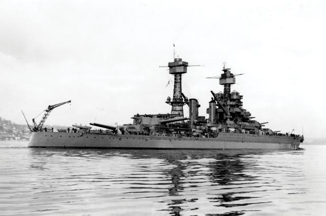
In the wake of the 1922 Washington Naval Treaty, the Navy began to reconstruct much of its battle fleet, primarily to incorporate protective measures allowed by the treaty (see “A Template for Peace,” pp. 34–39). Beginning in 1925, the six remaining “coal burner” battleships began modifications, starting with the four ships of the Florida (BB-30) and Wyoming (BB-32) classes. Among other changes, they had their cage mainmasts replaced by poles. The last pair, the New York (BB-34) class, received even more significant upgrades in 1926 to maintain their position in the battle line. Among them was the replacement of both cages with tall tripods at the fore and shorter tripods at the main.
The oil-burners were also upgraded, with the four ships of the Nevada (BB-36) and Pennsylvania (BB-38) classes receiving tall tripods fore and aft. Beginning in 1931, the three ships of the New Mexico (BB-40) class began modernization and, unlike other U.S. battleships, their foremasts were replaced by a massive tower constructions and the mains by poles. The Tennessee (BB-43) and Colorado (BB-45) classes retained their cages through the start of World War II.
The shape of the U.S. battle fleet changed in the aftermath of the Japanese attack at Pearl Harbor. By the end of the war, both cage masts and tripods virtually had disappeared. Fully half of the Navy’s 16 commissioned battleships were in the harbor on 7 December 1941; four were sunk, and three were seriously and one lightly damaged.
Of those sunk, the Arizona (BB-39) and Oklahoma (BB-37) were total losses. The West Virginia and California (BB-44) were under repair until 1944 and returned to combat as completely different ships with massive integrated tower structures reminiscent of the new South Dakotas (BB-57).
From August 1942 to August 1943, the Tennessee received a similar rework. The Nevada was rebuilt, incorporating her fore tripod into a greatly enlarged superstructure. Her mainmast was cut down below the level of her funnel. The Pennsylvania, although not needing any major reconstruction after the attack, was heavily modified in late 1942. This included the removal of her mainmast, which was replaced by a deckhouse and small pole. The Maryland (BB-46) retained her fore cage mast throughout the war, but her mainmast was replaced by a deckhouse and large pole. Her sister the Colorado (BB-45), which was not at Pearl Harbor at the time of the attack, received a nearly identical upgrade. Cages disappeared from the U.S. Navy with their decommissioning.
1. “The New Battleship Masts,” The Beaver [OK] Herald, 16 February 1911.
2. Norman Friedman, U.S. Battleships: An Illustrated Design History (Annapolis, MD: Naval Institute Press, 1985).
3. Richard H. M. Robinson, “Homer Clark Poundstone and the All-Big-Gun Battleship,” U.S. Naval Institute Proceedings 75, no. 1 (January 1949): 99–100.
4. “Florida Ready for ‘Battle,’” The New York Times, 26 May 1908; “Ready to Fire on Monitor,” The New York Times, 28 May 1908; “Turret of Florida Withstands Big Gun,” The New York Times, 28 May 1908; and “Victory for Turret,” New York Post, 28 May 1908.
5. “Test of Cage Mast Fire Control Tower,” The Iron Age 89, no. 6 (8 February 1912), 347–48.
6. “Doubt Concerning Basket Masts,” Popular Mechanics, April 1910, 518–19.
7. “Rear Admiral Hugh Rodman, Commander, Battleship Division Nine, to Secretary of the Navy Josephus Daniels, 19 May 1918” Naval History and Heritage Command, history.navy.mil/content/history/nhhc/research/publications/ documentary-histories/wwi/may-1918/rear-admiral-hugh-ro-0.html.
8. “Comparison of cage masts and tripod masts” [“Cage vs Tripod Masts in the USN”], The World War I Document Archive, gwpda.org/naval/cagvtrip.htm.


